background image

Using Admin

4-6

4.2 Cost Center tab

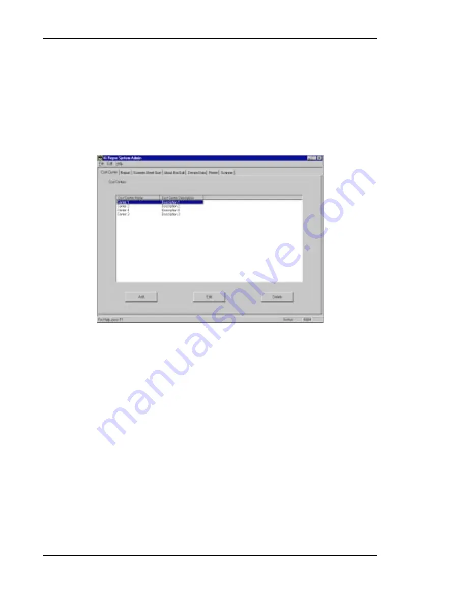
The Cost Center tab displays a list of cost center information. This tab also allows
cost centers to be added, edited or deleted.

Cost centers are used to record the usage status of plotter/scanner devices. The cost
center to be used for recording is specified from the Client application. Only the cost
centers defined under the Cost Center tab will be available for selection in the Client
application.

Содержание Xi3648

Страница 1: ...ION HANDBOOK ALWAYS read this Instruction Handbook thoroughly before use After reading maintain it in good condition and keep it together with the Instruction Handbook for your copier Published in Jul...

Страница 2: ......

Страница 3: ...Intel Corporation in the USA All other brand names and trade names used in this handbook are trademarks or registered trademarks of their respective owners Preface Xi Repro System is designed to conne...

Страница 4: ...tarting and closing the application 3 2 3 2 Creating and saving a project file 3 6 3 3 Sets members tree 3 9 3 4 Creating and deleting a new set 3 11 3 5 Inserting and deleting a plot 3 12 3 6 Display...

Страница 5: ...stamp 5 5 5 3 Editing a stamp 5 8 5 4 Checking the stamp 5 12 6 Network Plotting 6 1 Setting the Remote Client 6 3 6 2 Setting the Local Client 6 7 6 3 Checking Remote Client operation 6 8 6 4 Return...

Страница 6: ...This section provides an overview of Xi Repro System 1 1 Features 1 2 System configuration 1 3 Product components 1 4 System requirements 1 Overview...

Страница 7: ...rage of scanned image data in a file handles tasks including set number assignment and collating on a computer when printing plots and produce copies of sets in collated order Xi Repro System saves th...

Страница 8: ...s computer is called the Local Client Computers that have this software installed and use the copier connected to the Local Client are called Remote Clients The Local Client also provides Remote Clien...

Страница 9: ...ble Relay PCB 2 used during installation Relay cable used during installation Installation manual 1 3 2 CD ROM The supplied CD ROM contains Xi Repro System the program for plotter controller LittleBea...

Страница 10: ...t Print the requested number of copies of a file within a set Delete a set 2 Admin The Admin application is a system management tool for defining each device interfacing with Xi Repro System This appl...

Страница 11: ...following is the minimum equipment required to use a system with Xi Repro System Copier PointSource Xi 3648 Computer 200 MHz Pentium Pro Processor Microsoft Windows NT 4 0 Service Pack 3 must be inst...

Страница 12: ...This section describes the installation procedure 2 1 Connecting the machines 2 2 Installing Xi Repro System 2 3 Setting the copier 2 4 Checking operation 2 5 Other software 2 System Installation...

Страница 13: ...the system installation procedure for the Local Client See 6 Network Plotting for the installation procedure for the Remote Client Installing Xi Repro System Connecting the machines Checking operatio...

Страница 14: ...ocate an available PCI slot and remove its bracket and screw 3 Insert the interface card into the PCI slot by pressing it evenly until it sits correctly in the slot Check for correct insertion and sec...

Страница 15: ...Program Folder screen appears Click on the Next button The program group name can be changed to any desired name 8 The Start Copying Files screen appears Click on the Next button 9 The Setup Complete...

Страница 16: ...ng Left Leading Margin Enter On Line 2 3 Setting the copier Reset the offline status of the copier to use Xi Repro System Resetting the offline status of the copier 1 Press the added features key on t...

Страница 17: ...ter key 6 Press the mode set keys until the message 1 OFF LINE RELEASE appears 7 Press the enter key The offline status is reset and the on line indicator on the operation panel turns on 8 Press the a...

Страница 18: ...opier automatically returns to the on line mode if no copy is made for a certain period while the copier is offline Check the following before starting to control the copier via Xi Repro System or the...

Страница 19: ...setting of the copier is complete check for correct communication between the computer and copier by performing the following steps 1 Start Windows NT 2 Open the Start menu by clicking on Start in th...

Страница 20: ...een Check the following if the Status OK message is not displayed in the Local System Status screen Is the copier power turned on Is the copier offline status reset Is the copier on line indicator tur...

Страница 21: ...etails Notes To use Xi Repro System on a network ensure that the Windows NT network is configured correctly To use Xi Repro System locally where no network adapter is installed configure it as follows...

Страница 22: ...eating and deleting a new set 3 5 Inserting and deleting a plot 3 6 Displaying and editing a plot 3 7 Inserting and deleting a stamp 3 8 Editing a stamp 3 9 Inserting and deleting a pen set 3 10 Chang...

Страница 23: ...not provide a scanner facility 3 1 Starting and closing the application 3 1 1 Starting the application Perform the following steps to start the application 1 Click on Start in the task bar to open the...

Страница 24: ...oolbar 3 Sets members tree of a project 4 Buttons for printing scanning 5 Buttons to change the placement of set members 6 Box in which a plot thumbnail is displayed 7 Box in which a message indicatin...

Страница 25: ...rform the following steps to select the units system used in the application 1 Click on Tools in the menu bar to open the Tools menu 2 Click on Options 3 Select the Preferences tab then the units syst...

Страница 26: ...Using Client 3 5 3 1 4 Closing the application Perform the following steps to close the application 1 Click on File in the menu bar to open the File menu 2 Click on Exit...

Страница 27: ...2 1 Creating a new project file When Client is started it creates a new project called Untitled A new project can also be created by either of the following methods Click on New and then Project from...

Страница 28: ...e toolbar 2 Specify the directory enter the filename and then click on the Save button A project is saved as a project file with the rfx extension A project file is simply a list of the names of plots...

Страница 29: ...ient 3 8 3 2 3 Opening an existing project file 1 Click on Open from File in the menu bar or the button in the toolbar 2 Select the project to be opened and click on the Open button The project window...

Страница 30: ...inting is enabled by adding an image file to the sets members tree The Client application is used for adding a plot stamp and pen set to and deleting them from the sets members tree and for defining p...

Страница 31: ...e formats 4 Pen set Used when selecting pens for printing can be set when a plot is a vector file format 5 Stamp Useful for printing the date and operator names over the plot file image Since stamps a...

Страница 32: ...new set is created as a sub set of the currently selected set 3 4 2 Changing a set name A new set is automatically named New Set To change the name select the set in the sets members tree and click on...

Страница 33: ...mage file as a plot into a set 1 Select the set where the image is inserted from the sets members tree 2 Select Image in the Insert menu or click on the button in the toolbar The file select dialog bo...

Страница 34: ...ion plot select the plot to be displayed from the sets members tree and select Image Editor in the Tools menu or click on the button in the toolbar The image editor is started and the image of the ras...

Страница 35: ...members tree 2 Select Modify in the Edit menu The Modify Plot dialog box is displayed 3 Check the item to be converted in Transformations Select Despeckle to remove small speckles see 9 2 Technical n...

Страница 36: ...le to save the edited data as a new file having a different name Select Modify Raster File to save the edited data over the raster file 6 Click on the OK button When Modify Source Plot File is selecte...

Страница 37: ...ck on the in the toolbar The image editor is then started and a raster file image is displayed Edit the raster file using the image editor A raster file can also be edited by clicking on the Edit butt...

Страница 38: ...plot can be applied to that plot only Perform the following steps when inserting a stamp 1 Select the set or plot from the sets members tree into which a stamp is to be inserted 2 Select Stamp from t...

Страница 39: ...enu The Stamp tab is then displayed and the setting can be changed see 3 13 7 Stamp tab To edit a stamp select the stamp file to be edited from the sets members tree and select Stamp Editor in the Too...

Страница 40: ...n a plot can be applied only to that plot Perform the following steps when inserting a pen set 1 Select a set or plot from the sets members tree into which a pen set is to be inserted 2 Select Pen set...

Страница 41: ...members in a set Perform the following steps when moving a member 1 Select the member to be moved from the sets members tree 2 Click on the Up Down buttons on the project window to move the member It...

Страница 42: ...data Perform the following steps when printing 1 When using the setting and plotter for the previous print job proceed to step 6 Select Options from the Tools menu and then the Accounting tab 2 Assign...

Страница 43: ...click on the Print button on the project window or button in the toolbar The print dialog box is displayed 5 Select the printer in Destination 6 Set the number of copies and copying order in Copies 7...

Страница 44: ...il to is selected when using a remote printer via e mail Enter an e mail address to which the print job is sent in the box When auto dialing to the remote access server RAS type the location to be dia...

Страница 45: ...cribes how to use Admin 4 1 Starting and closing the application 4 2 Cost Center tab 4 3 Report tab 4 4 Scanner Sheet Size tab 4 5 About Box Edit tab 4 6 Device Data tab 4 7 Printer tab 4 8 Scanner ta...

Страница 46: ...istrator window This chapter describes how to use each of these tabs 4 1 Starting and closing the application 4 1 1 Starting the application Perform the following steps to start the application 1 Clic...

Страница 47: ...describes the Administrator window which appears when the application starts 1 Menu bar Used when closing the Admin application changing the units system used in Admin or viewing Help 2 Status bar Di...

Страница 48: ...1 3 Selecting the units system Perform the following steps to select the units system 1 Click on Edit in the menu bar to open the Edit menu 2 Click on Preferences 3 Select the units system to be used...

Страница 49: ...Using Admin 4 5 4 1 4 Closing the application Perform the following steps to close the application 1 Click on File in the menu bar to open the File menu 2 Click on Exit...

Страница 50: ...ws cost centers to be added edited or deleted Cost centers are used to record the usage status of plotter scanner devices The cost center to be used for recording is specified from the Client applicat...

Страница 51: ...er name must have 20 characters or less and a cost center description must have 80 characters or less 4 2 2 Editing a cost center Select the cost center to be edited from the list of cost centers and...

Страница 52: ...e plotter device whose usage status is to be reported Cost Center Select the cost center whose usage status record is to be reported Cost centers available for selection are defined under the Cost Cen...

Страница 53: ...iewer The text editor program to be used for viewing the report The text editor can be selected by clicking on the Browse button Database Parameters Clicking on this button displays the Database Param...

Страница 54: ...er sheet sizes This tab also allows scanner sheet sizes to be added edited or deleted The sheet names defined under this tab are used in the Scan dialog of the Client application Sheet Name The sheet...

Страница 55: ...ay be set to any value between 1 000000 and 36 000000 Y height may be set to any value between 1 000000 and 392 913333 4 4 2 Editing a scanner sheet size Select the scanner sheet size to be edited fro...

Страница 56: ...allows creation and editing of the text displayed when About is selected from the Help menu of the Admin Client or Stamp applications The text created or edited under this tab is saved in the databas...

Страница 57: ...ys the model names of the devices OpMode Indicates whether a device is to be used only as a printer only as a scanner or as both The code 1 means it is used only as a printer 2 means only as a scanner...

Страница 58: ...n the box then click on the OK button The Name and Enabled boxes are available in this software version In other versions they are unavailable and displayed only A Device ID may be set to 6 7 or 8 A N...

Страница 59: ...ists the device IDs of all devices that have been defined as printers The Device IDs displayed here are the same as the Device IDs defined under the Device Data tab Resolution Shows the printer resolu...

Страница 60: ...e printer automatically switches over to a new paper roll when it has run out of paper Shows 1 when Auto Rollover is enabled or 0 when disabled Min Scale Factor Shows the minimum scale factor availabl...

Страница 61: ...t have been defined as a scanner The Device ID displayed here is the same as the Device ID defined under the Device Data tab Resolution Shows the scanning resolution in dots per inch dpi Scan Settings...

Страница 62: ...when disabled Auto Exposure Indicates if automatic exposure is enabled 1 when enabled or 0 when disabled Min Scale Factor Shows the minimum scale factor available for scanning Max Scale Factor Shows...

Страница 63: ...This section describes how to use Stamp 5 1 Starting and closing the application 5 2 Creating and saving a stamp 5 3 Editing a stamp 5 4 Checking the stamp 5 Using Stamp...

Страница 64: ...ion 5 1 1 Starting the application Perform the following steps to start the application 1 Click on Start in the task bar to open the Start menu 2 Select Programs and then Xi Repro System 3 Click on St...

Страница 65: ...ction 1 Menu bar 2 Toolbar 3 Font selection bar 4 Edit Text box 5 Insert Parameters box 6 Preview box 7 Sets the rotation angle of a character 8 Sets the rotation angle of the entire text 9 Comment bo...

Страница 66: ...Using Stamp 5 4 5 1 3 Closing the application Perform the following steps to close the application 1 Click on File in the menu bar to open the File menu 2 Click on Exit...

Страница 67: ...g a stamp 5 2 1 Creating a new stamp When Stamp is started it creates a new stamp called Untitled A new stamp can also be created by either of the following methods Click on New from File in the menu...

Страница 68: ...2 Saving a stamp 1 Click on Save from File in the menu bar or the button in the toolbar 2 Specify the directory enter the filename and then click on the Save button A stamp is saved as a stamp file wi...

Страница 69: ...amp 5 7 5 2 3 Opening an existing stamp 1 Click on Open from File in the menu bar or the button in the toolbar 2 Select the stamp to be opened and click on the Open button The Text Stamp Editor window...

Страница 70: ...t as a stamp Click the mouse at the desired position and type the text Right clicking in the Edit Text box shows the edit menu enabling cutting pasting or copying of the text When parameters are inser...

Страница 71: ...dificationDate The date when the file was modified ModificationTime The time when the file was modified CurrentDate The date when the plot file was printed CurrentTime The time when the plot file was...

Страница 72: ...down list box The font size can be selected from the fixed sizes between 8 and 72 points or specified by typing a number between 1 and 1638 points 5 3 4 Changing the letter style Change the style by...

Страница 73: ...to any angle between 0 and 360 degrees Specify the angle by clicking on or or typing a number Base rotation Rotates the entire text to the specified angle The line can be rotated anticlockwise to any...

Страница 74: ...Using Stamp 5 12 5 4 Checking the stamp Check the printing status of the edited stamp in the Preview box...

Страница 75: ...This section describes plotter setting for network use 6 1 Setting the Remote Client 6 2 Setting the Local Client 6 3 Checking Remote Client operation 6 4 Returning to local mode 6 Network Plotting...

Страница 76: ...work mode the Local Client serves as a plotter server to receive print jobs from other network Clients namely Remote Clients and prints them on the connected plotter In the network mode the Local Clie...

Страница 77: ...r normal operation and click on the Next button 7 The Select Program Folder screen appears Click on the Next button The program group name can be changed to another name if so desired 8 The Start Copy...

Страница 78: ...inter To use the plotter on the network at a Remote Client printer configuration must be performed Configure the printer as follows 1 Click Start in the task bar to open the Start menu 2 Click Printer...

Страница 79: ...Network Plotting 6 5 4 Select Network printer server and click Next 5 The Connect to Printer dialog box opens Select the plotter connected to the server and click OK...

Страница 80: ...Network Plotting 6 6 6 Select whether to configure the plotter as the default printer and click Next 7 Click Finish 8 An icon for the configured plotter appears in the Printers folder...

Страница 81: ...e plotter server the Local Client must be in the network mode To enter network mode perform the following steps 1 Start the Local Client application 2 Select Network from the Mode menu or click on the...

Страница 82: ...nd the plotter server by performing the following steps after making the Remote Client and Local Client settings 1 Start Windows NT 2 Open the Start menu by clicking on Start in the task bar 3 Select...

Страница 83: ...nication is good the Status OK message is displayed at the top right of the screen 7 Click on the Close button to close the screen If the Status OK message is not displayed in the Network System Statu...

Страница 84: ...to return to local mode Immediately Click on this button to return to local mode even in the middle of the current plot After Current Plot Click on this button to return to local mode after the curre...

Страница 85: ...This section describes troubleshooting procedures 7 1 Troubleshooting 7 Troubleshooting...

Страница 86: ...copier is on If it is turn it off by pressing the on line key If the Print Problems dialog box is dis played follow the instructions to remove the cause Check if the Windows NT network is con figured...

Страница 87: ...This section describes the specifications of Xi Repro System 8 1 Basic specifications 8 2 Hardware specifications 8 3 Software specifications 8 4 Interface specifications Specifications 8...

Страница 88: ...nterface card Pentium Pro 200 MHz or faster 128 MB 2 GB or more Windows NT 4 0 and Service Pack 3 CAD graphics software that can store files in HPGL HPGL 2 TIFF Calcomp BMP and WMF formats is required...

Страница 89: ...the printing and scanning job history An application that creates stamp files that can be inserted into plot files An application that controls the plotter scanner 10 C 50 F 35 C 95 F 15 85 RH Less t...

Страница 90: ...ations 8 4 8 2 Hardware specifications PCI card 5 V DC 5 Less than 0 85 A Depends on the computer power source Voltage Current Power consumption Item Specifications Remarks PCI controller interface ca...

Страница 91: ...optional drawer 3 drawers and bypass Paper vellum and film Available Selected between 9 areas 3 long 3 wide Offset from leading or trailing edge 0 00 36 00 Offset from right or left edge 0 00 36 00 R...

Страница 92: ...s Available 25 400 Setting available Setting available 0 90 180 and 270 Thumbnail view after scanning TIFF Item Specifications Remarks Sizes Length specification Scanning density Continuous scanning S...

Страница 93: ...ed between 9 areas 3 long 3 wide Offset from the leading or trailing edge 36 00 36 00 Offset from the right or left edge 36 00 36 00 Reference Longitudinal direction Lateral direction Item Specificati...

Страница 94: ...y connecting the internal copier relay cable to the relay PCB 118 shielded Interface card Video 80 pin Copier Video 100 pin Item Specifications Remarks PCI controller interface card Video terminal Int...

Страница 95: ...Useful information is listed in this section 9 1 The LittleBear driver 9 2 Technical notes 9 3 Pen patterns 9 4 Plot file formats 9 Appendices...

Страница 96: ...onto the computer beforehand This device driver works as the mediator between the higher level software Xi Repro System and the hardware interface card Xi Repro System never talks directly to the inte...

Страница 97: ...d graphics are removed while leaving the solid areas intact The despeckle operation performs a 3 3 median filter on the image For each 3 3 neighborhood of pixels in the original image a single pixel i...

Страница 98: ...dat file as 16 16 pixel blocks The pattern file can be modified to add additional patterns In general patterns 0 through 15 are designed to be used for line work Patterns 16 through 29 are designed f...

Страница 99: ...Appendices 9 5 Figure 9 1 Pen patterns 0 1 2 3 4 5 6 7 8 9 10 11 12 13 14 15 16 17 18 19 20 21 22 23 24 25 26 27 28 29 30 31...

Страница 100: ...e formats The following is a list of file formats accepted for plotting by Xi Repro System Only monochrome images 1 bit per pixel can be printed BMP BMP Calcomp HPGL HP HPGL PLT HPGL 2 HP HPGL PLT TIF...

Страница 101: ...e at his own expense CAUTION The changes or modifications not expressly approved by the party responsible for compliance could void the user s authority to operate the equipment The above warning is v...

Страница 102: ...This machine has passed all quality controls and final inspection...

Страница 103: ...ion 1500 Oakbrook Drive Norcross Georgia 30093 TEL 770 729 9786 FAX 770 729 9873 Southwestern Region 2825 West Story Road Irving Texas 75038 5299 TEL 972 550 8987 FAX 972 570 4704 Dallas Parts Distrib...

Отзывы: