background image

2MH/2MJ/2MK/2ML

1-5-2

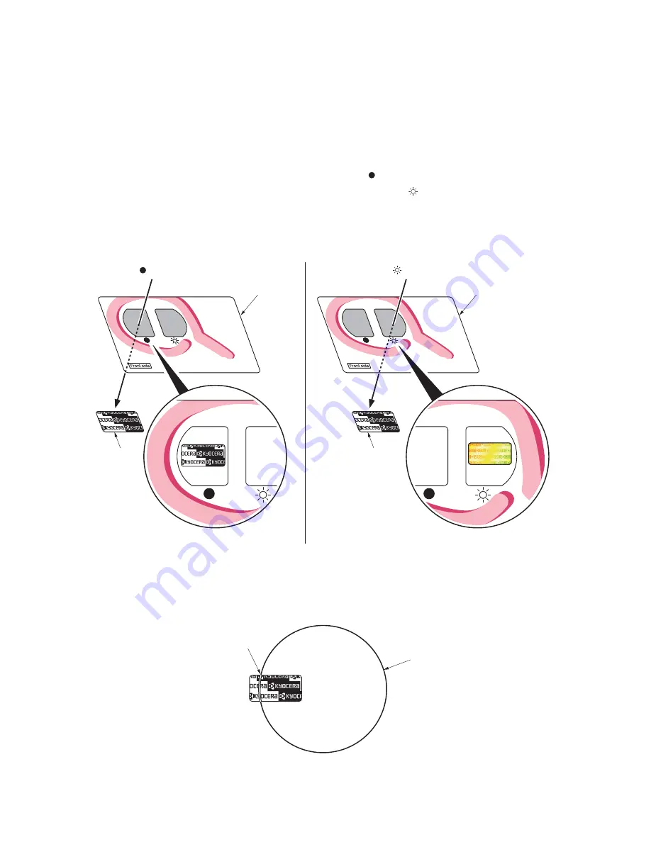
(4) How to tell a genuine Kyocera Mita toner container

As a means of brand protection, the Kyocera Mita toner container utilizes an optical security technology to 
enable visual validation. A validation viewer is required to accomplish this.
Hold the validation viewer over the left side part of the brand protection seal on the toner container. Through 
each window of the validation viewer, the left side part of the seal should be seen as follows:

A black-colored band when seen through the left side window (

)

A shiny or gold-colored band when seen through the right side window (

)

The above will reveal that the toner container is a genuine Kyocera Mita branded toner container, otherwise, it 
is a counterfeit.

Figure 1-5-1 

The brand protection seal has an incision as shown below to prohibit reuse.

Figure 1-5-2 

Validation viewer

Validation viewer

Brand
protection
seal

Brand
protection
seal

See through the left window
 (    marking)

See through the right window
(    marking)

A shiny or gold-colored band when
seen through the right side window

A black-colored band when
seen through the left side window

Incision

Cut

Содержание ECOSYS FS-1035MFP/DP

Страница 1: ...SERVICE MANUAL Published in May 2012 2MHSM062 Rev 2 FS 1030MPF FS 1030MFP DP FS 1035MFP DP FS 1130MFP FS 1135MFP ...

Страница 2: ...LISEES SELON LES INSTRUCTIONS DONNEES Il peut être illégal de jeter les batteries dans des eaux d égout municipales Vérifiez avec les fonctionnaires municipaux de votre région pour les détails concernant des déchets solides et une mise au rebut appropriée Notation of products in the manual For the purpose of this service manual products are identified by print speed and presence of FAX FS 1030MFP ...

Страница 3: ...Revision history Revision Date Replaced pages Remarks 1 24 April 2012 Contents 1 1 2 1 1 3 1 3 21 2 4 13 to 20 Address 2 25 May 2012 Contents 1 4 2 to 6 ...

Страница 4: ...This page is intentionally left blank ...

Страница 5: ...rsonnel to ensure the safety of their customers their machines as well as themselves during maintenance activities Service personnel are advised to read this booklet carefully to familiarize themselves with the warnings and precautions described here before engaging in maintenance activities ...

Страница 6: ... this symbol CAUTION Bodily injury or damage to property may result from insufficient attention to or incorrect com pliance with warning messages using this symbol Symbols The triangle symbol indicates a warning including danger and caution The specific point of attention is shown inside the symbol General warning Warning of risk of electric shock Warning of high temperature indicates a prohibited...

Страница 7: ...d or dusty place This may cause fire or electric shock Do not install the copier near a radiator heater other heat source or near flammable material This may cause fire Allow sufficient space around the copier to allow the ventilation grills to keep the machine as cool as possible Insufficient ventilation may cause heat buildup and poor copying performance Always handle the machine by the correct ...

Страница 8: ... carefully Always check that the copier is correctly connected to an outlet with a ground connection Check that the power cable covering is free of damage Check that the power plug is dust free If it is dirty clean it to remove the risk of fire or electric shock Never attempt to disassemble the optical unit in machines using lasers Leaking laser light may damage eyesight Handle the charger section...

Страница 9: ... caution labels that should be present on the machine according to the instruction handbook are clean and not peeling Replace with new ones if necessary Handle greases and solvents with care by following the instructions below Use only a small amount of solvent at a time being careful not to spill Wipe spills off completely Ventilate the room well while using grease or solvents Allow applied solve...

Страница 10: ...This page is intentionally left blank ...

Страница 11: ...e mode 1 3 55 1 4 Troubleshooting 1 4 1 Paper misfeed detection 1 4 1 1 Paper misfeed indication 1 4 1 2 Paper misfeed detection condition 1 4 2 1 4 2 Self diagnostic function 1 4 7 1 Self diagnostic function 1 4 7 2 Self diagnostic codes 1 4 8 1 4 3 Image formation problems 1 4 17 1 Completely blank printout 1 4 18 2 All black printout 1 4 19 3 Dropouts 1 4 19 4 Black dots 1 4 20 5 Black horizont...

Страница 12: ...he paper feed assembly paper feed roller and pickup roller 1 5 6 2 Detaching and refitting the retard roller assembly 1 5 8 3 Detaching and refitting the MP paper feed roller 1 5 10 4 Note on removing and Installing the upper registration roller and lower registration roller 1 5 12 1 5 4 Optical section 1 5 13 1 Detaching and refitting the DP 1 5 13 2 Detaching and refitting the scanner unit 1 5 1...

Страница 13: ...on 2 1 1 2 MP tray paper feed section 2 1 2 3 Paper conveying section 2 1 3 2 1 2 Drum section 2 1 4 1 Drum section 2 1 4 2 Main charger unit 2 1 5 2 1 3 Optical section 2 1 6 1 Scanner unit 2 1 6 2 Image scanner unit ISU 2 1 7 3 Laser scanner unit 2 1 9 2 1 4 Developing section 2 1 11 2 1 5 Transfer separation section 2 1 13 2 1 6 Cleaning section 2 1 14 2 1 7 Fuser section 2 1 16 2 1 8 Paper exi...

Страница 14: ...4 Appendixes 2 4 1 Appendixes 2 4 1 1 Wiring diagram 2 4 1 2 Repetitive defects gauge 2 4 3 3 Maintenance parts list 2 4 4 4 Firmware Environment Commands 2 4 5 5 Maintenance Commands 2 4 13 INSTALLATION GUIDE PAPER FEEDER ...

Страница 15: ... tray A4 A5 A6 B5 ISO B5 Letter Legal Statement Executive Oficio II Folio 16K 216 340 Custom Zoom level Manual mode 25 to 400 1 increments Auto mode 400 200 141 129 115 90 86 78 70 64 50 25 Copying speed When using the DP Cassette A4R 20 sheets min LetterR 21 sheets min Leagal 17 sheets min B5R 22 sheets min A5R 17 sheets min When the DP is not used Cassette A4R 30 sheets min 35 sheets min 30 shee...

Страница 16: ...urce halogen heater Abnormally high temperature protection devices thermostat CPU PowerPC440 667MHz Main memory Standard 256 MB Maximum 768 MB Interface Standard USB interface connector 1 USB Hi speed USB host 1 Network interface 1 10BASE T 100BASE TX Option KUIO W slot 1 It uses it by fax in 4in1 model Resolution Reading 600 600 dpi Writing 600 600 dpi Operating envi ronment Tempera ture 10 to 32...

Страница 17: ...min Leagal 16 sheets min 18 sheets min First print time A4 feed from cassette 6 0 s or less 7 0 s or less 6 0 s or less 7 0 s or less Resolution Fast 1200 600 dpi 300 dpi Fine 1200 Fast 1200 600 dpi 300 dpi Operating system Windows 2000 Windows XP Windows XP Professional Windows Server 2003 Windows Server 2003 x64 Edition Windows Vista x86 Edition Windows Vista x64 Edition Windows 7 x86 Edition Wi...

Страница 18: ...scape 300 dpi Image quality Text Photo original Duplex B W 18 images min Color 8 images min A4 landscape 300 dpi Image quality Text Photo original Interface Ethernet 10 BASE T 100 BASE TX USB2 0 Hi Speed USB Network protocol TCP IP Transmission system PC transmission SMB Scan to PC E mail SMTP Scan to E mail FTP transmission FTP FTP over SSL Scan to FTP USB transmission USB Scan to USB TWAIN scan ...

Страница 19: ...IS A5 Legal Letter Statement Oficio II 216x340 Automatic document feed Max 50 sheets Scanner resolution Horizontal Vertical 200 100 dpi Normal 8 dot mm 3 85 line mm 200 200 dpi Fine 8 dot mm 7 7 line mm 200 400 dpi Super fine 8 dot mm 15 4 line mm 400 400 dpi Ultra fine 16 dot mm 15 4 line mm Printing resolution 600 600 dpi Gradations 256 shades One Touch key 22 keys Multi Station transmission Max...

Страница 20: ...p cover 5 Front cover 6 Main charger cleaner 7 Drum unit 8 Lock lever 9 Toner container 10 Top tray 11 Paper length guide 12 Paper stopper 13 Paper width guides 14 Cassette 15 Paper width guides MP tray 16 MP Multi Purpose tray 17 MP tray extension 18 USB Interface connector 19 Network Interface connector 20 Tel connector T1 1 21 Line connector L1 1 22 Rear cover 23 Power switch 24 Power cord conn...

Страница 21: ...ecall Pause key 6 Confirm Destination key 7 Add Destination key 8 On Hook key 9 One touch keys 10 Message display 11 Document Box key LED 12 FAX key LED 13 Send key LED 14 Shift Lock key LED 15 Left Select key 16 Processing indicator 17 Memory indicator 18 Right Select key 19 Function Menu key LED 20 Numeric keys 21 Clear key 22 Reset key 23 Attention indicator 24 Back key 25 OK key 26 Cursor keys...

Страница 22: ...ML 1 1 8 3 Option Figure 1 1 3 System Kit Expention memory for copy and printer General purpose 144pin DIMM 1 slot Card Authentication Kit B Network interface Kit IB 23 3in1 model only 1 2 2 1 Machine 2 Paper feeder ...

Страница 23: ... Paper path Paper path option Light path 1 Cassette 2 MP tray 3 Paper feed conveying section 4 Toner container 5 Developer unit 6 Main charger unit 7 Drum unit 8 Laser scanner unit LSU 9 Transfer separation section 10 Fuser section 11 Exit section 12 Duplex conveying section 13 Scanner section ...

Страница 24: ...2MH 2MJ 2MK 2ML 1 1 10 Figure 1 1 5 Only model with Document Processor as standard 14 15 Original path Light path 14 Image scanner unit ISU 15 Document processor DP ...

Страница 25: ...2MH 2MJ 2MK 2ML 1 1 11 This page is intentionally left blank ...

Страница 26: ...nd cool or hot direct air Avoid places subject to dust and vibrations Choose a surface capable of supporting the weight of the machine Place the machine on a level surface maximum allowance inclination 1 Avoid air borne substances that may adversely affect the machine or degrade the photoconductor such as mercury acidic of alkaline vapors inorganic gasses NOx SOx gases and chlorine based organic s...

Страница 27: ...5 Bottom pad R 6 Machine cover 7 Top pad L 8 Top pad R 9 Accessory spacer 10 Toner container 11 Plastic bag 12 Power cord 13 Plastic bag 250 600 14 Operation labels 15 Operation label pad 16 Plastic bag 240 350 17 Plastic bag 18 Ferrite core 19 Modular cable 20 Quick installation guide 21 Safety guide 1 22 Safety guide 2 23 Toner OSHA leaflet 24 EEA information leaflet 25 DVD ROM 120 V AC model on...

Страница 28: ... Procedure 1 Remove two tapes 2 Open the sheet Figure 1 2 3 3 Remove two tapes A 4 Open the top cover 5 Remove the tape B and then remove the spacer 6 Close the top cover Figure 1 2 4 Sheet Tape Tape Sheet Tape B Tape A Top cover Tape A Spacer ...

Страница 29: ...2MH 2MJ 2MK 2ML 1 2 4 7 Remove two tapes Figure 1 2 5 8 Open the DP 9 Remove the sheet 10 Remove the paper Figure 1 2 6 Tape Tape DP Sheet Paper ...

Страница 30: ... A 12 Move the lock lever to the position of release When turning on power if the lock lever is not released the error message is displayed 13 Close the DP 14 Remove eight tapes B Figure 1 2 7 Tapes B Tapes B Tapes B Tapes B Tape A Lock lever ...

Страница 31: ...ory slot cover 5 Insert the expansion memory into the memory socket so that the notches on the memory align with the correspond ing protrusions in the slot 6 Close the memory slot cover 7 Secure the screw 8 Refit the right side cover 9 Print a status page to check the mem ory expansion If memory expansion has been properly performed information on the installed memory is printed with the total mem...

Страница 32: ...r the maintenance item number using the cursor left right keys or numeric keys The selected maintenance item is run Press the stop key Press the start key Start End Maintenance mode is entered The maintenance item is selected Maintenance mode is exited and the system is restarted to initialize it and to reflect the setting changes Repeat the same maintenance item Run another maintenance item Turn ...

Страница 33: ...the scanner automatically U425 Setting the target Fax U600 Initializing all data U601 Initializing permanent data U603 Setting user data 1 DTMF U604 Setting user data 2 2 120 V 1 220 240 V U605 Clearing data U610 Setting system 1 Setting the number of lines to be ignored when receiving a fax at 100 magnification Setting the number of lines to be ignored when receiving a fax in the auto reduction m...

Страница 34: ...CNG detection times in the fax telephone auto select mode OFF ON ON 2TIME U633 Setting communication control 4 Enabling disabling V 34 communication Setting the V 34 symbol speed 3429 Hz Setting the number of times of DIS signal reception Setting the reference for RTN signal output ON ON ONCE 15 U634 Setting communication control 5 0 U640 Setting communication time 1 Setting the one shot detection...

Страница 35: ... dial tone detection Setting busy tone detection Setting for a PBX Setting the loop current detection before dialing PSTN ON ON LOOP ON U670 Outputting lists U695 FAX function customize ON OFF U699 Setting the software switches Others U910 Clearing the black ratio data U917 Setting backup data reading writing U927 Clearing the all copy counts and machine life counts one time only U977 Data capture...

Страница 36: ...enter the settings after initialization or replacement Method 1 Press the start key 2 Select the item to be output using the cursor up down keys 3 Press the start key A list is output Method Send to the USB memory 1 Turn the power switch off 2 Insert USB memory in USB memory slot 3 Turn the power switch on 4 Enter the maintenance item 5 Press the start key 6 Select the item to be send 7 Select TEX...

Страница 37: ...08 01 01 1000 01 08 01 02 1000 01 08 01 01 1000 01 08 01 02 1000 01 08 01 01 1000 01 08 01 02 1000 01 08 01 01 1000 01 08 01 02 1000 01 08 01 01 1000 01 08 01 02 1000 01 08 01 01 1000 01 08 01 02 1000 01 08 01 01 1000 01 08 01 02 Service Call Log 8 7 6 5 4 3 2 1 Count 1881214 178944 5296 5295 2099 1054 809 30 Service Code 01 0030 01 1010 01 4000 01 3100 01 2000 01 2000 01 2500 01 2500 Maintenance ...

Страница 38: ... up request time out 0107 Waiting for fuser package to be ready 0110 Top cover open 0501 No paper feed from cassette 1 0502 No paper feed from cassette 2 0503 No paper feed from cassette 3 0508 No paper feed from duplex section 0509 No paper feed from MP tray 0511 Multiple sheets in cassette 1 0512 Multiple sheets in cassette 2 0513 Multiple sheets in cassette 3 0518 Multiple sheets in duplex sect...

Страница 39: ...sette 2 4303 Duplex sensor non arrival jam cassette 3 4308 Duplex sensor non arrival jam duplex 4309 Duplex sensor non arrival jam MP tray 4311 Duplex sensor stay jam cassette 1 4312 Duplex sensor stay jam cassette 2 4313 Duplex sensor stay jam cassette 3 4318 Duplex sensor stay jam duplex 4319 Duplex sensor stay jam MP tray 9000 No original feed 9001 DP original conveying jam 9003 DP original swi...

Страница 40: ...e 2 35 Western type 4 d Detail of paper type Hexadecimal 01 Plain 02 Transparency 03 Preprinted 04 Labels 05 Bond 06 Recycled 07 Vellum 08 Rough 09 Letterhead 0A Color 0B Prepunched 0C Envelope 0D Cardstock 0E Coated 0F 2nd side 10 Media 16 11 High quality 15 Custom 1 16 Custom 2 17 Custom 3 18 Custom 4 19 Custom 5 1A Custom 6 1B Custom 7 1C Custom 8 e Detail of paper eject location Hexadecimal 01...

Страница 41: ...etection are logged The total page count at the time of the Toner Empty error with using an unknown toner con tainer Unknown toner log code 1 byte 2 cate gories First byte 01 Fixed Toner con tainer Second byte 00 Fixed Black 11 Counter Log Comprised of three log coun ters including paper jams self diagnostics errors and replacement of the toner con tainer f Paper jam g Self diagnostic error h Main...

Страница 42: ...ing the machine number Description Sets or displays the machine number Purpose To check or set the machine number Method 1 Press the start key If the machine serial number of engine PWB matches with that of main PWB If the machine serial number of engine PWB does not match with that of main PWB Setting Carry out if the machine serial number does not match 1 Press EXECUTE 2 Press the start key Writ...

Страница 43: ...he cursor up down keys 6 Press the start key The operation starts 7 To stop continuous operation press the stop key Completion Press the stop key The screen for selecting a maintenance item No is displayed Item No Description Display Description NORMAL SPEED Normal reading 600 dpi HIGH SPEED High speed reading Display Description CCD ADP NON P Without paper single sided original of CCD continuous ...

Страница 44: ...e To check and change the maintenance cycle Method 1 Press the start key The currently set maintenance cycle is displayed Setting 1 Select M CNT A using the cursor up down keys 2 Change the setting using the cursor left right keys or numeric keys 3 Press the start key The value is set Clearing 1 Select CLEAR using the cursor up down keys 2 Press the start key The count is cleared Completion Press ...

Страница 45: ...The maintenance count is displayed Setting 1 Select M CNT A using the cursor up down keys 2 Change the setting using the cursor left right keys or numeric keys 3 Press the start key The count is set Clearing 1 Select CLEAR using the cursor up down keys 2 Press the start key The count is cleared Completion Press the stop key The screen for selecting a maintenance item No is displayed Item No Descri...

Страница 46: ...cording to the preference of the user copy service provider if folio size paper is to be counted as one sheet single count or two sheets double count Setting 1 Press the start key 2 Select the count system using the cursor up down keys Initial setting DBL COUNT FOLIO 3 Press the start key The setting is set Completion Press the stop key The screen for selecting a maintenance item No is displayed I...

Страница 47: ... No is displayed U285 Setting service status page Description Determines displaying the digital dot coverage report on reporting Purpose According to user request changes the setting Setting 1 Press the start key 2 Select ON or OFF using the cursor up down keys Initial setting ON 3 Press the start key The setting is set Completion Press the stop key The screen for selecting a maintenance item No i...

Страница 48: ...ance is about to be reached by setting the number of copies that can be made before the current maintenance cycle ends When the difference between the number of copies of the maintenance cycle and that of the maintenance count reaches the set value the message is displayed Purpose To change the time for maintenance due indication Setting 1 Press the start key 2 Select COUNT using the cursor up dow...

Страница 49: ...K is displayed If a problem occurs during auto adjustment NG XX XX is replaced by an error code is displayed and operation stops Should this happen determine the details of the problem and repeat the procedure from the beginning 7 To return to the screen for selecting an item press the stop key Method DP 1 Select ADJUST DP using the cursor up down keys 2 Set a specified original P N 303LJ57010 in ...

Страница 50: ...ck band is not detected DP main scanning direction magnification near end 0a Black band is not detected DP auxiliary scanning direction magnification leading edge 0b Black band is not detected DP auxiliary scanning direction magnification leading edge original check 0c Black band is not detected DP auxiliary scanning direction trailing edge 0d Black band is not detected DP auxiliary scanning direc...

Страница 51: ... Display Description N875 Setting the N875 patch for the original for adjustment N475 Setting the N475 patch for the original for adjustment N125 Setting the N125 patch for the original for adjustment CYAN Setting the cyan patch for the original for adjustment MAGENTA Setting the magenta patch for the original for adjustment YELLOW Setting the yellow patch for the original for adjustment RED Setti...

Страница 52: ...the edge to the black belt c of the original at D 50 mm from the left edge E 105 mm from the left edge and F 160 mm from the left edge respec tively 2 Apply the following formula for the values obtained D F 2 E 2 5 Enter the values solved using the cursor left right keys or numeric keys in SUB LEAD 6 Press the start key The value is set 7 Measure the length G from the edge of the black belt b to e...

Страница 53: ...s the start key There is no operation necessary on this screen The destination code and the OEM code are displayed with the values currently set 5 Press the start key Data initialization starts To cancel data initialization press the stop key 6 After data initialization the entered destination OEM codes and ROM version are displayed A ROM version displays three kinds application boot and IPL Desti...

Страница 54: ... are displayed with the values currently set 5 Press the start key Data initialization starts To cancel data initialization press the back key 6 After data initialization the entered destination OEM codes and ROM version are displayed A ROM version displays three kinds application boot and IPL U603 Setting user data 1 Description Makes user settings to enable the use of the machine as a fax Purpos...

Страница 55: ...ithout any ringing 4 Press the start key The value is set Completion Press the stop key The screen for selecting a maintenance item No is displayed U605 Clearing data Description Initializes data related to the fax transmission such as transmission history Purpose To clear the transmission history Method 1 Press the start key 2 Select CLEAR COM REC 3 Press the start key Initialization processing s...

Страница 56: ... received data volume exceeds the record ing capacity when the data is recorded in the auto reduction mode If the number of excess lines is below the setting those lines are ignored If over the setting the entire data on a page is fur ther reduced so that it can be recorded on the same page 1 Change the setting using the cursor left right keys or numeric keys Increase the setting if a page receive...

Страница 57: ...n a page is further reduced so that it can be recorded on the same page 1 Change the setting using the cursor left right keys or numeric keys Increase the setting if a page received in the reduction mode is over reduced and too much trailing edge margin is left Decrease it if the received image does not include all transmitted data 2 Press the start key The value is set Completion Press the stop k...

Страница 58: ...etter size paper is set Sets the number of adjustment lines for automatic reduction when letter size paper is set 1 Change the setting using the cursor left right keys or numeric keys 2 Press the start key The value is set Completion Press the stop key The screen for selecting a maintenance item No is displayed Item No Description Display Description ADJ LINES Sets the number of adjustment lines f...

Страница 59: ...s if the protocol list is automatically printed out 1 Select the setting using the cursor left right keys Initial setting OFF 2 Press the start key The setting is set Item No Description Display Description AUTO REDUCTION Selects if auto reduction in the auxiliary direction is to be per formed PROTOCOL LIST Sets the automatic printing of the protocol list DETECT TRAIL Sets the detection of trailin...

Страница 60: ...remote switching mode Description Sets the signal detection method for remote switching Be sure to change the setting according to the type of telephone connected to the machine Setting 1 Press the start key 2 Select REMORT MODE and press the start key 3 Select the mode using the cursor up down keys Initial setting ONE 4 Press the start key The setting is set Completion Press the stop key The scre...

Страница 61: ...redialing interval 1 Change the setting using the cursor left right keys 2 Press the start key The value is set U625 Setting the number of times of auto redialing 1 Change the setting using the cursor left right keys or numeric keys 2 Press the start key The value is set Completion Press the stop key The screen for selecting a maintenance item No is displayed Item No Description Display Descriptio...

Страница 62: ... is selected for transmission regardless of this setting 1 Select the setting using the cursor up down keys Initial setting 14400bps V17 2 Press the start key The setting is set Item No Description Display Description TX SPEED Sets the communication starting speed RX SPEED Sets the reception speed TX ECHO Sets the waiting period to prevent echo problems at the sender RX ECHO Sets the waiting perio...

Страница 63: ... the start key The setting is set Setting the waiting period to prevent echo problems at the receiver Sets the period before an NSF CSI or DIS signal is sent after a CED signal is received Used when problems occur due to echoes at the receiver 1 Select the setting using the cursor up down keys Initial setting 75 2 Press the start key The setting is set Completion Press the stop key The screen for ...

Страница 64: ...ng to the IP Internet Protocol telephone line 1 Select the setting using the cursor up down keys Initial setting ON 2 Press the start key The setting is set Setting the frequency of the CED signal Sets the frequency of the CED signal Used as one of the measures to improve transmission per formance for international communications 1 Select the setting using the cursor up down keys Initial setting 2...

Страница 65: ...transmission is received when an auto switching device is attached to the machine communication problems including auto switching inability sometimes occur Change the setting to ignore short protocol transmission to prevent such problems 1 Select the setting using the cursor up down keys Initial setting ON 2 Press the start key The setting is set Item No Description Display Description DIS 4BYTE S...

Страница 66: ...rsor up down keys Enabling disabling V 34 communication Sets whether V 34 communication is enabled disabled for transmission and reception 1 Select the setting using the cursor up down keys Initial setting ON 2 Press the start key The setting is set Item No Description Display Description 1TIME Detects CNG once 2TIMES Detects CNG twice Display Description V 34 Enables or disables V 34 communicatio...

Страница 67: ...g the reference for RTN signal output Sets the error line rate as the reference for RTN signal output If transmission errors occur fre quently due to the quality of the line they can be reduced by lowering this setting 1 Select the setting using the cursor up down keys Initial setting 15 2 Press the start key The setting is set Completion Press the stop key The screen for selecting a maintenance i...

Страница 68: ...but the setting made is ineffective Method 1 Press the start key 2 Select the item to be set using the cursor up down keys Setting the one shot detection time for remote switching 1 Change the setting using the cursor left right keys 2 Press the start key The value is set Setting the continuous detection time for remote switching 1 Change the setting using the cursor left right keys 2 Press the st...

Страница 69: ... the cursor left right keys 2 Press the start key The value is set Setting the T1 time out time Sets the time before receiving the correct signal after call reception No change is necessary for this maintenance item 1 Change the setting using the cursor left right keys 2 Press the start key The value is set Item No Description Display Description T0 TIME OUT Sets the T0 time out time T1 TIME OUT S...

Страница 70: ...ephone fails to receive a call 1 Change the setting using the cursor left right keys 2 Press the start key The value is set Figure 1 3 3 Ta Tb1 Tb2 time out time Setting the Tb1 time out time In the fax telephone auto select mode sets the time to start sending the ring back tone after receiving a call as a fax machine see figure 1 3 3 In fax telephone auto select mode change the setting when fax r...

Страница 71: ...successful or a telephone fails to receive a call 1 Change the setting using the cursor left right keys 2 Press the start key The value is set Setting the Td time out time Sets the length of the time required to determine silent status fax one of the triggers for Tc time check In the TAD mode change the setting when fax reception is unsuccessful or a telephone fails to receive a call Be sure not t...

Страница 72: ...wn keys Initial setting 0dB 2 Press the start key The setting is set Setting the G3 reception cable equalizer 1 Select 0dB 4dB 8dB or 12dB using the cursor up down keys Initial setting 0dB 2 Press the start key The setting is set Setting the modem detection level 1 Select 33dBm 38dBm 43dBm or 48dBm using the cursor up down keys Initial setting 43dBm 2 Press the start key The setting is set Complet...

Страница 73: ... cursor up down keys 3 Change the setting using the cursor left right keys or numeric keys 4 Press the start key The setting is set Completion Press the stop key The screen for selecting a maintenance item No is displayed Item No Description Display Description Setting range Initial setting SGL LV MDM Modem output level 1 to 15 9 120 V 10 220 240 V DTMF LV C DTMF output level main value 0 to 15 0 ...

Страница 74: ... PSTN dial tone detection Selects if the dial tone is detected to check the telephone is off the hook when a fax is connected to a public switched telephone network 1 Select the setting using the cursor up down keys Initial setting ON 2 Press the start key The setting is set Item No Description Display Description EXCHANGE Sets the connection to PBX PSTN DIAL TONE Sets PSTN dial tone detection BUS...

Страница 75: ...hen connected to a PBX According to the type of the PBX connected select the mode to connect an outside call 1 Select the setting using the cursor up down keys Initial setting LOOP 2 Press the start key The setting is set Setting the loop current detection before dialing Sets if the loop current detection is performed before dialing 1 Select the setting using the cursor up down keys Initial settin...

Страница 76: ...en for selecting a maintenance item No is displayed Item No Description Display Description SETTING LIST Outputs a list of software switches self telephone number confidential boxes ROM versions and other information ACTION LIST Outputs a list of error history transmission line details and other information SELF ST REPORT Outputs a list of settings in maintenance mode own status report regarding f...

Страница 77: ...et Setting A5 PT PRI CHG 1 Select ON or OFF using the cursor left right keys Initial setting OFF 2 Press the start key The setting is set Completion Press the stop key The screen for selecting a maintenance item No is displayed Item No Description Display Description FAX BULK TX fax batch transmission ON OFF A5 PT PRI CHG Change of print size priority at the time of small size reception Display De...

Страница 78: ...bit between 0 and 1 5 Press the start key to set the value Completion Press the stop key The screen for selecting a maintenance item No is displayed List of Software Switches of Which the Setting Can Be Changed Communication control procedure Item No Description No Bit Item 36 7654 Coding format in transmission 3210 Coding format in reception 37 5 33600 bps V34 4 31200 bps V34 3 28800 bps V34 2 26...

Страница 79: ...ne detection pattern 122 7654 Busy tone detection pattern 1 Busy tone detection in automatic FAX TEL switching 125 76543210 Access code registration for connection to PSTN 126 7654 FAX TEL automatic switching ringback tone ON OFF cycle No Bit Item 133 76543210 DTMF signal transmission time 134 76543210 DTMF signal pause time 141 76543210 Ringer detection cycle minimum 142 76543210 Ringer detection...

Страница 80: ...pose To clear data as required at times such as during maintenance service Method 1 Press the start key 2 Select ALL CLEAR using the cursor up down keys 3 Press the start key The accumulated black ratio data is cleared Completion Press the stop key The screen for selecting a maintenance item No is displayed Item No Description ...

Страница 81: ...n those assigned are also retrieved or written in 8 Select ON using the cursor left right keys 9 Press the start key Starts reading or writing The progress of selected item is displayed in When an error occurs the operation is canceled and an error code is displayed 10 When normally completed FIN is displayed 11 Turn the power switch off and on after completing writing when selecting IMPORT Item N...

Страница 82: ... e113 Job accounting error in writing e510 Program error in writing e114 Job accounting list error e511 Program error in reading e115 Job accounting list error e710 Fax memory open error e210 One touch open error e711 Fax memory initialization error e211 One touch list error e712 Fax memory list error e212 One touch list error e713 Fax memory error e310 User managements backup error e714 Fax memor...

Страница 83: ... Supplement The total account counter and the machine life counter can be cleared only once if all count val ues are 1000 or less Method 1 Press the start key 2 Press EXECUTE 3 Press the start key All copy counts and machine life counts are cleared CAN NOT EXECUTE is displayed if the count cannot be cleared Completion Press the stop key The screen for selecting a maintenance item No is displayed I...

Страница 84: ...o the machine Method 1 Insert USB memory in USB memory slot 2 Turn the power switch on 3 Enter the maintenance item 4 Press the start key 5 Select EXECUTE 6 Press the start key 7 Send the print data to the machine Once the print data is stored into USB memory OK will be displayed Completion Press the stop key The screen for selecting a maintenance item No is displayed Item No Description ...

Страница 85: ...ng a service mode Press the System Menu Counter key Select Adjust Maint using the cursor up down keys and press the start key The selected service mode is run Press the stop key Select Service Setting using the cursor up down keys and press the start key Start End The Sys Menu Count menu appears The Adjust Maint menu appears The Service Setting menu appears ...

Страница 86: ...service purpose The status page includes various settings and service cumulative Purpose To acquire the current printing environmental parameters and cumulative information Method 1 Enter the Service Setting menu 2 Select Service Status using the cursor up down keys 3 Press the start key 4 Press Yes the Left Select key Two pages will be printed Completion Press the stop key ...

Страница 87: ...ons Document Processor Memory Card Card Authentication Kit B Installed Not Installed Installed FAX Information Rings Normal Rings FAX TEL Rings TAD 3 3 3 Print Coverage Average Total K 1 10 Copy K 1 10 Printer K 1 10 FAX K 1 10 Period Last Page Usage Page A4 Letter Conversion 1111111 11 1111111 11 1111111 11 1111111 11 27 10 2009 03 11 2009 08 40 1 00 FRPO Status User Top Margin User Left Margin P...

Страница 88: ...000000 0000000 0000000 0000000 0000000 F00 U00 0 0 0 30 30 70 70 00 abcde 1 0 0000 0000 0000 0000 0000 0000 0000 0000 0000 0000 0000 0000 0000 0000 0000 0000 0000 0000 0000 0000 0000 0000 0000 0000 0000 12345678 11223344 00001234abcd567800001234abcd5678 01234567890123456789012345678901 0008 00 07 2MH_D100 001 005 t ABCDEFGHIJ ABCDEFGHIJ ABCDEFGHIJ 0000000000 F80C001A37 302A183C00 000100013D 8791BE...

Страница 89: ...ocument processor 14 Presence or absence of the optional paper feeder Paper feeder 2 Paper feeder 3 15 Presence or absence of the optional memory card 16 Presence or absence of the card authentication kit B 17 Page of relation to the A4 Letter 18 Average coverage for total 19 Average coverage for copy 20 Average coverage for printer 21 Average coverage for fax 22 Cleared date and output date 23 Co...

Страница 90: ...Asterisk NG b Database version c The oldest time stamp of database version d Consistency of the present software version and the ME firmware version _ underscore OK Asterisk NG e ME firmware version f The oldest time stamp of the ME database ver sion Normal if a and d are underscored and b and e are identical with c and f 33 Scanner firmware version 34 Fax firmware version 35 Mac address 36 Number...

Страница 91: ...0 Not installed 1 Full speed 2 Hi speed 48 Paper handling information 0 Paper source unit select 1 Paper source unit 49 Black and white printing double count mode 0 All single counts 3 Folio Single count Less than 330 mm length 50 Billing counting timing 51 Temperature machine inside 52 Temperature machine outside 53 Relative temperature machine outside 54 Absolute temperature machineoutside 55 LX...

Страница 92: ...on infor mation 62 Toner installation mode information 63 Soft version of the optional paper feeder 64 Version of the optional message 65 Maintenance information 66 Durm ID 67 Counter of the developer drive time 68 Counter of the drum drive time 69 Drum serial number Code conversion A B C D E F G H I J 0 1 2 3 4 5 6 7 8 9 ...

Страница 93: ... Press Yes in the confirmation display Network status page will be printed Completion Press the stop key New Developer Perform the toner installation of the developer unit Description Perform the toner installation when the developer unit has been replaced Purpose Perform when the developer unit is replaced Method 1 Enter the Service Setting menu 2 Select New Developer using the cursor up down key...

Страница 94: ...Press the start key The setting is set 6 Press the start key Data initialization starts Destination code list Completion Press the stop key Service items Description Code Destination Code Destination 000 Japan 253 CTR21 European nations 009 Australia Italy 038 China Germany 080 Hong Kong Spain 084 Indonesia U K 088 Israel Netherlands 097 Korea Sweden 108 Malaysia France 126 New Zealand Austria 136...

Страница 95: ...ys 2 Press the start key 3 Select PBX or PSTN using the cursor up down keys 4 Press the start key The setting is set Setting for PBX 1 Select PBX Setting using the cursor up down keys 2 Press the start key 3 Select Loop Flash or Earth using the cursor up down keys 4 Press the start key The setting is set Setting access code to PSTN 1 Select Dial No to PSTN using the cursor up down keys 2 Press the...

Страница 96: ...Service Setting menu 2 Select Remote Diag Set using the cursor up down keys 3 Press the start key 4 Select On using the cursor up down keys 5 Press the start key The setting is set 6 Select Remote Diag ID using the cursor up down keys 7 Press the start key 8 Enter the prespecified remote diagnostics ID number 0000 to 9999 using the numeric keys 9 Press the start key The setting is set Completion P...

Страница 97: ...2MH 2MJ 2MK 2ML 1 3 66 This page is intentionally left blank ...

Страница 98: ...curs the machine immediately stops printing and displays the paper misfeed mes sage on the operation panel To remove paper misfed in the machine pull out the paper cassette open the front cover rear cover or duplexer s cover or remove the drum unit Figure 1 4 1 Paper misfeed indication Help Paper jammed in the printer JAM ...

Страница 99: ...3 Paper feeder Cassette 1 DP 1 Registration sensor RS 2 Paper sensor PS 3 MP paper sensor MPPS 4 Exit sensor ES 5 PF paper feed sensor 1 PFPFS1 6 PF paper sensor 1 PFPS1 7 PF paper feed sensor 2 PFPFS2 8 PF paper sensor 2 PFPS2 9 DP document sensor DPOS 10 DP timing sensor DPTS 2 3 1 4 5 6 7 8 10 9 A B C D E F G H ...

Страница 100: ...tion sensor RS does not turn off dur ing paper feed from cassette 1 E 0512 Multiple sheets in cassette 2 PF paper feed sensor 1 PFPFS1 does not turn off during paper feed from cassette 2 B 0513 Multiple sheets in cassette 3 PF paper feed sensor 2 PFPFS2 does not turn off during paper feed from cassette 3 C 0518 Multiple sheets in duplex section The registration sensor RS does not turn off dur ing ...

Страница 101: ... cassette 3 E 4208 The eject sensor ES does not turn on during paper feed from duplex section E 4209 The eject sensor ES does not turn on during paper feed from MP tray E 4211 Eject sensor stay jam The eject sensor ES does not turn off during paper feed from cassette 1 G 4212 The eject sensor ES does not turn off during paper feed from cassette 2 G 4213 The eject sensor ES does not turn off during...

Страница 102: ... 4313 The eject sensor ES does not turn off after a switchback start during paper feed from cassette 3 F 4318 The eject sensor ES does not turn off after a switchback start during paper feed from duplex section F 4319 The duplex sensor DUS does not turn off after a switchback start during paper feed from the MP tray F 9000 No paper feed from DP DP timing sensor DPTS does not turn on during origina...

Страница 103: ...4 6 9410 DP timing sensor stay jam The DP timing sensor DPTS does not turned off within the specified time its turning on H Code Contents Conditions Jam location Refer to figure 1 4 2 for paper jam location see page 1 4 2 ...

Страница 104: ...m is detected the machine stops print ing and display an error message on the operation panel An error message consists of a message prompting a contact to service personnel total print count and a four digit error code indicating the type of the error The display varies depending on the type of the error Figure 1 4 3 Machine failure Call service C ...

Страница 105: ...PWB See page 1 5 37 0120 MAC address data error Defective flash memory Replace the control PWB See page 1 5 37 0130 Backup memory read write error Defective flash memory Replace the control PWB See page 1 5 37 Defective control PWB Replace the control PWB See page 1 5 37 0140 Backup memory data error Defective flash memory Replace the control PWB See page 1 5 37 Defective control PWB Replace the c...

Страница 106: ...tive har ness between PF main PWB YC5 and paper feeder interface connec tor or improper connector inser tion Reinsert the connector Also check for continuity within the connector har ness If none remedy or replace the harness Refer to the service manual for the paper feeder Defective PF mainPWB Replace the PF main PWB Refer to the service manual for the paper feeder 0830 FAX control PWB flash prog...

Страница 107: ... the connector har ness If none remedy or replace the harness See page 1 5 37 Defective drive transmission sys tem of the main motor Check if the rollers and gears rotate smoothly If not grease the bushings and gears Check for broken gears and replace if any Defective main motor Replace the main motor See page 1 5 49 Defective control PWB Replace the control PWB See page 1 5 37 2610 PF paper feed ...

Страница 108: ...tor Replace the PF main motor Refer to the service manual for the paper feeder Defective control PWB Replace the control PWB See page 1 5 37 3100 ISU home position error Defective FFC between CCD PWB YC1 and control PWB YC8 Replace the image scanner unit ISU See page 1 5 21 Defective FFC between control PWB YC6 and scanner PWB YC103 or improper FFC insertion Reinsert the FFC Also check for conti n...

Страница 109: ...ness between LED drive PWB YC2 and expo sure lamp or improper con nector insertion Reinsert the connector Also check for continuity within the connector har ness If none remedy or replace the harness Defective expo sure lamp Replace the exposure lamp See page 1 5 27 Defective LED drive PWB Replace the LED drive PWB See page 1 5 27 Defective control PWB Replace the control PWB See page 1 5 37 3300 ...

Страница 110: ...ion Reinsert the connector Also check for continuity within the connector har ness If none remedy or replace the harness Defective laser scanner unit Replace the laser scanner unit See page 1 5 17 Defective control PWB Replace the control PWB See page 1 5 37 4200 BD error laser scanner unit error BD sensor does not detect laser beam due to con densation on the polygon mirror Turn machine power off...

Страница 111: ... Abnormally high fuser thermistor temperature Fuser thermistor detects abnormally temperature Shorted fuser thermistor Replace the fuser unit See page 1 5 32 Defective control PWB Replace the control PWB See page 1 5 37 6030 Broken fuser thermistor wire Input from fuser thermistor is 0 A D value Poor contact in the fuser therm istor connector terminals Reinsert the connector See page 1 5 32 Broken...

Страница 112: ...tage PWB YC201 Reinsert the connector Defective power source PWB Replace the power source PWB See page 1 5 40 Defective control PWB Replace the control PWB See page 1 5 37 7990 Waste toner full The waste toner sensor has detected that the waste toner reser voir drum unit is full Waste toner res ervoir drum unit is full Turn the power switch off on to restart the machine If the error is not resolve...

Страница 113: ... Defective control PWB Turn the power switch off on to restart the machine If the error is not resolved replace control PWB See page 1 5 37 F041 Control PWB scanner PWB com munication error A communication error is detected Defective control PWB or scanner PWB Turn the power switch off on to restart the machine If the error is not resolved replace control PWB or scanner PWB See page 1 5 37 or 1 5 ...

Страница 114: ...4 19 See page 1 4 19 See page 1 4 20 See page 1 4 20 6 Black vertical streaks 7 Unsharpness 8 Gray back ground 9 Dirt on the top edge or back of the paper 10 Undulated printing at the right edge scanning start position See page 1 4 20 See page 1 4 21 See page 1 4 21 See page 1 4 21 See page 1 4 22 ABC 123 ABC 123 ABC 123 ABC 123 ABC 123 ABC 123 This vertical line should be straight ...

Страница 115: ...5 27 Investigate that the terminals between the main charger unit and the drum unit are not in loose contact See page 1 5 28 Defective transfer bias output or developer bias output Replace the high voltage PWB See page 1 5 43 Poor contact of developer bias terminal spring and high volt age output terminal B J401 J402 J403 on the high voltage PWB Poor contact of transfer bias ter minal spring and t...

Страница 116: ...efects occur at regular intervals of 62 8 mm 2 1 2 See page 2 4 3 the problem may be the damaged developer roller in the developer unit Replace the developer unit See page 1 5 27 Defective drum unit If the defects occur at regular intervals of 94 mm 3 11 16 See page 2 4 3 the problem may be the damaged drum in the drum unit Replace the drum unit See page 1 5 28 Defective fuser unit heat roller or ...

Страница 117: ...that the drum shaft and the grounding tab machine are in good contact Apply the grounding tab a small amount of electroconductive grease as required Defective drum unit Replace the drum unit See page 1 5 28 Print example Causes Check procedures corrective measures Adhesion of oxide to main char ger wire Remove the drum unit See page 1 5 28 Slide the charger cleaner green left and right 2 or 3 time...

Страница 118: ...ing The print density may be set too high Try adjusting the print density For details refer to the operation guide Defective potential on the drum surface Replace the drum unit See page 1 5 28 Defective main charger grid Clean the main charger grid See page 1 5 29 Defective developer roller developer unit If a developer unit which is known to work normally is available for check replace the curren...

Страница 119: ...nning start position Print example Causes Check procedures corrective measures Defective polygon motor laser scanner unit Replace the laser scanner unit See page 1 5 17 Defective control PWB Replace the control PWB See page 1 5 37 This vertical line should be straight ...

Страница 120: ... See page 1 5 40 8 Defective power source PWB Replace the power source PWB See page 1 5 40 9 Defective control PWB Replace the control PWB See page 1 5 37 2 Right cooling fan motor does not operate 1 Broken right cooling fan motor coil Check for continuity across the coil If none replace the right cooling fan motor 2 Defective harness between right cooling fan motor and control PWB YC27 or imprope...

Страница 121: ... If none remedy or replace the harness 3 Defective control PWB Replace the control PWB See page 1 5 37 6 Paper feed clutch does not operate 1 Broken paper feed clutch coil Check for continuity across the coil If none replace the paper feed clutch 2 Defective harness between paper feed clutch and control PWB YC20 or improper connector insertion Reinsert the connector Also check for continuity withi...

Страница 122: ...ector Also check for continuity within the connector harness If none remedy or replace the harness 3 Defective control PWB Replace the control PWB See page 1 5 37 10 Cleaning lamp does not turn on 1 Defective harness between cleaning lamp YC701 and control PWB YC28 or improper connec tor insertion Reinsert the connector Also check for continuity within the connector harness If none remedy or repla...

Страница 123: ...gh voltage PWB Replace the high voltage PWB See page 1 5 43 3 Defective exit sen sor Replace the exit sensor 13 Attention indi cator is lit when the front cover is closed 1 Defective interlock switch on the power source PWB Check for continuity across the interlock switch If there is no continuity when the interlock switch is on replace the power source PWB See page 1 5 40 14 When the trou ble occ...

Страница 124: ...parator pad or MPF sepa ration pad is worn Replace the separator pad if it is worn Check if the paper is curled Replace the paper 5 Paper jams Check if the paper is excessively curled Replace the paper Check if the contact between the upper and lower registration rollers is correct Check visually and remedy if necessary Check if the heat roller or press roller is extremely dirty or deformed Replac...

Страница 125: ...erly shared 1103 Destined host folder and or file names are invalid 1 Check illegal characters are not contained within these names 2 Check the name of the folder and files conform with the naming syntax 3 Confirm destined host and folder 1105 SMB protocol is not enabled 1 Confirm device s SMB protocols 2101 Login to the host has failed 1 Confirm the destined host 2 Confirm that the LAN cable is p...

Страница 126: ...FTP port number 4 Confirm device s network parameters 5 Confirm the network parameters the device is con nected 6 Check the FTP server name 2102 Access to the FTP server has failed Connection timeout 1 Check the FTP server name 2 Check the FTP port number 3 Confirm device s network parameters 4 Confirm the network parameters the device is con nected 5 Check the FTP server name 2103 The server cann...

Страница 127: ...rm device s network parameters 2 Confirm the network parameters the device is con nected 3101 FTP server responded with an error 1 Confirm device s network parameters 2 Confirm the network parameters the device is con nected 3 Check the FTP server Code Contents Check procedures corrective measures ...

Страница 128: ...n to the SMTP POP3 server has failed Connection timeout 1 Check the SMTP POP3 server name 2 Check the SMTP POP3 port number 3 Confirm device s network parameters 4 Confirm the network parameters the device is con nected 5 Check the SMTP POP3 server 2103 The server cannot establish communi cation 1 Check the SMTP POP3 server name 2 Check the SMTP POP3 port number 3 Confirm device s network paramete...

Страница 129: ...lish the SSL session 1 Verify the self certificate of the device 2 Check the server certificate of the SMTP POP3 server 3 Check the SMTP POP3 configuration of the device and the SMTP POP3 server Code Contents Check procedures corrective measures ...

Страница 130: ...ion errors start with an E indica tion followed by five digits The upper three of the five digits indicate general classification of the error and its cause while the lower two indicate the detailed classification Items for which detailed classification is not necessary have 00 as the last two digits Figure 1 4 4 Error code U X X X X X Detailed classification of error code General classification o...

Страница 131: ...ission in V 34 mode See page 1 4 42 U018XX A communication error occurred before starting T 30 protocol during reception in V 34 mode See page 1 4 43 U02000 Relay broadcast was refused by a relay station because of a mismatch in permit ID num ber and permit telephone number when a relay command was issued U02100 A relay command failed because the destination unit relay station had no relay broad c...

Страница 132: ...d for confidential transmission was not registered in the des tination unit Or in interoffice subaddress based transmission mode the specified sub address box number was not registered in the destination unit Or the destination was being accessed U04100 Confidential transmission failed because the destination unit had no confidential capabil ity Or subaddress based transmission failed because the ...

Страница 133: ...l reception memory overflowed U14100 Memory overflowed in the destination unit during confidential transmission Or in interof fice subaddress based transmission memory overflowed in the destination unit U19000 Memory overflowed during memory reception U19100 Memory overflowed in the destination unit during transmission U19200 Memory transmission failed because a decoding error occurred U19300 Tran...

Страница 134: ...ubaddress confidential box U00434 Confidential polling request was received but interrupted because the specified confi dential box No was intended for encryption U00435 Confidential polling request was received but interrupted because the specified confi dential box was being accessed Or subaddress based bulletin board transmission request was received but interrupted because the specified subadd...

Страница 135: ...ecording paper U00615 Empty of recording paper U00620 Copier fixing unit problem U00622 Copier drive motor problem U00655 CTS was not activated after RTS due to a modem error U00656 Data was not transmitted after CTS was activated due to a modem error U00670 Power was cut off during communication U00677 There was no file to transmit in the memory transmission mode U00690 System error Error code De...

Страница 136: ...1017 No relevant signal was received after transmission of an EOP signal and the preset number of command retransfers was exceeded U01018 No relevant signal was received after transmission of a PRI EOP signal and the preset number of command retransfers was exceeded U01019 No relevant signal was received after transmission of a CNC signal and the preset num ber of command retransfers was exceeded ...

Страница 137: ...n EOR Q signal ECM U01052 A DCN signal was received after transmission of an RR signal ECM U01053 A DCN signal was received after transmission of a PPS NULL signal ECM U01054 A DCN signal was received after transmission of a PPS MPS signal ECM U01055 A DCN signal was received after transmission of a PPS EOM signal ECM U01056 A DCN signal was received after transmission of a PPS EOP signal ECM U010...

Страница 138: ...e after transmission of a PIP signal U01124 No response after transmission of a PIN signal U01125 No response after transmission of a CNS signal between units of our make U01126 No response after transmission of a PPR signal ECM U01127 No response after transmission of an ERR signal ECM U01128 No response after transmission of an RNR signal ECM U01129 No response after transmission of an SPA signa...

Страница 139: ...al ECM U01154 A DCN signal was received after transmission of an RNR signal ECM U01155 A DCN signal was received after transmission of an SPA signal short protocol U01160 During message reception transmission time exceeded the maximum transmission time per line U01161 Number of error lines exceeded limits during message reception U01162 A break in loop current was detected during message reception...

Страница 140: ...mmunication speed and symbol speed occurs after MPh exchange a DCN signal was transmitted to the destination unit and the line was cut 2 9 U023XX error code table Relay command abnormal reception 2 10 U044XX error code table Encrypted transmission Error code Description U01800 A communication error occurred in phase 2 line probing U01810 A communication error occurred in phase 3 primary channel eq...

Страница 141: ...2MH 2MJ 2MK 2ML 1 4 44 This page is intentionally left blank ...

Страница 142: ...the hook Take care not to get the cables caught To reassemble the parts use the original screws If the types and the sizes of screws are not known refer to the PARTS LIST 2 Drum unit Note the following when handling or storing the drum unit When removing the drum unit never expose the drum surface to strong direct light Do not leave it for a long time even if it is weak light such as fluorescent l...

Страница 143: ...ollows A black colored band when seen through the left side window A shiny or gold colored band when seen through the right side window The above will reveal that the toner container is a genuine Kyocera Mita branded toner container otherwise it is a counterfeit Figure 1 5 1 The brand protection seal has an incision as shown below to prohibit reuse Figure 1 5 2 Validation viewer Validation viewer ...

Страница 144: ...e 1 Remove the screw 2 Unhook four hooks and then remove the rear upper cover Figure 1 5 3 3 Remove the cassette See page 1 5 6 4 Open the front cover 5 Unhook the hook and then remove the controller box cover Figure 1 5 4 Screw Hook Hook Hook Hook Rear upper cover Rear upper cover Controller box cover Hook ...

Страница 145: ...2MH 2MJ 2MK 2ML 1 5 4 6 Unhook seven hooks and then remove the right cover Figure 1 5 5 Right cover Right cover Right cover Hook Hook Hook Hook Hook Hook Hook ...

Страница 146: ...2MH 2MJ 2MK 2ML 1 5 5 7 Unhook six hooks and then remove the left cover Figure 1 5 6 Left cover Left cover Left cover Hook Hook Hook Hook Hook Hook ...

Страница 147: ...ing the paper feed assembly paper feed roller and pickup roller Procedure 1 Remove the cassette Figure 1 5 7 2 Slide the feed shaft 3 While pressing the lever and then remove the paper feed roller assembly Figure 1 5 8 Cassette Lever Feed shaft Paper feed roller assembly ...

Страница 148: ...d refit all the removed parts When refitting the paper feed roller assembly be sure to align the paper feed roller pivot with the slotted hole on the feed shaft Figure 1 5 9 Paper feed roller assembly Paper feed roller assembly Feed shaft Feed shaft Pivot Slotted hole ...

Страница 149: ...ove the cassette See page 1 5 6 2 Push the bottom plate down until it locks 3 Unhook two hooks and then remove the retard guide Figure 1 5 10 4 Remove the retard roller assembly Figure 1 5 11 Retard guide Retard guide Cassestte Cassette Hook Hook Hook Hook Bottom plate Retard roller Assembly ...

Страница 150: ...the retard roller assembly and refit all the removed parts Caution Before refitting the retard roller assembly firmly install the spring onto the projection of the retard roller assem bly Figure 1 5 12 Spring Retard roller assembly Projection ...

Страница 151: ...e MP paper feed roller Procedure 1 Open the front cover 2 Pull the MP feed holder lever down 1 3 Slide the MP feed holder 2 4 Remove the MP paper feed roller 3 Figure 1 5 13 2 3 MP feed holder Lever Front cover MP paper feed roller MPpaper feed roller 1 ...

Страница 152: ... the MP paper feed roller be sure to align the paper feed roller pivot with the slotted hole on the MPF feed shaft When refitting the MP paper feed roller be sure to align the MPF feed shaft pivot with the slotted hole on the MP paper feed roller Figure 1 5 14 MPF feed shaft Pivot MP paper feed roller Slotted hole ...

Страница 153: ...ration roller or lower registration roller be sure to use a new registration L spring and registration R spring Otherwise paper feeding may be deteriorated due to the spring hooks possi bly being distorted during the spring is unhooked Figure 1 5 15 Upper registration roller Lower registration roller Registration Lspring New Registration R spring New ...

Страница 154: ...2MH 2MJ 2MK 2ML 1 5 13 1 5 4 Optical section 1 Detaching and refitting the DP Procedure 1 Pull the DP out Figure 1 5 16 DP ...

Страница 155: ...page 1 5 13 2 Remove the left cover and right cover See page 1 5 3 3 Remove the FFC and connector from the control PWB 4 Remove three connectors from the scanner PWB Figure 1 5 17 Connector FFC Scanner PWB Scanner PWB Connector Connector Connector YC8 YC7 YC108 YC104 YC105 Control PWB Control PWB ...

Страница 156: ...2MH 2MJ 2MK 2ML 1 5 15 5 Release three clamps and then remove the wires Figure 1 5 18 6 Remove two screws Figure 1 5 19 Wires Wires Clamp Clamp Clamp Screw Screw Screw Screw ...

Страница 157: ...2MH 2MJ 2MK 2ML 1 5 16 7 Unhook four hooks and then remove the scanner unit Figure 1 5 20 Scanner unit Hooks Hooks ...

Страница 158: ... Remove the scanner unit See page 1 5 14 2 Remove the screw and then remove the grounding terminal 3 Remove three connectors from the con trol PWB Figure 1 5 21 Control PWB Connectors Connector YC3 YC10 YC32 Screw Grounding terminal Connector YC10 Connector YC3 Control PWB Connector YC32 ...

Страница 159: ...nector from the power source PWB Figure 1 5 22 6 Unhook four hooks and then remove the frame left duct 7 Remove the wires from the clamp Figure 1 5 23 Clamp Clamps Connector Power source PWB Power source PWB YC106 Frame left duct Frame left duct Hook Hook Clamp Wires Hook Hook ...

Страница 160: ...ease the hook and then remove the top cover rack L from the top cover Figure 1 5 24 9 Remove four screws from the top cover Figure 1 5 25 Top cover rack L Top cover Top cover Top cover rack L Hook Top cover Screw Screw Screw Screw ...

Страница 161: ... 1 5 26 11 Release the clamp and then pull out the wires 12 Remove four screws and then remove the laser scanner unit LSU 13 Check or replace the laser scanner unit LSU and refit all the removed parts Figure 1 5 27 T op cover Hook Hook Laser scanner unit Wires Clamp Screws Screws ...

Страница 162: ...page 1 5 13 2 Unhook two hooks by using a flat screwdriver from the pits 3 Remove the connector and then remove the operation panel Figure 1 5 28 4 Remove two screws 5 Unhook three hooks and then remove the ISU upper frame Figure 1 5 29 Hook Pit Pit Connector Operation panel Operation panel Hook ISU upper frame Screw Screw Hooks ...

Страница 163: ...t 8 Pull the ISU shaft out from the ISU Figure 1 5 30 9 Remove the ISU belt from the tension pulley and ISU gear 63 32 10 Remove the ISU belt from the hooks of the ISU Figure 1 5 31 Holder Image scanner unit ISU ISU shaft ISU shaft ISU shaft Image scanner unit ISU ISU belt ISU belt Hook Hook ISU belt ISU gear 63 32 Tension pulley ISU belt ...

Страница 164: ...ve the FFC center stopper Figure 1 5 32 12 Remove the FFC from the FFC tape D 13 Remove the ferrite core from the pit 14 Remove the FFC from the FFC tape A Figure 1 5 33 FFC center stopper Ferrite core FFC tape A Pit FFC FFC tape D ...

Страница 165: ...om the ISU lower frame 16 Remove the FFC tape D and A from the ISU lower frame 17 Clean the adhesive residue of the FFC tape D and A Figure 1 5 34 18 Remove the ferrite core from the FFC Figure 1 5 35 FFC FFC ISU lower frame ISU lower frame FFC tape A FFC tape D Ferrite core FFC ...

Страница 166: ...e Sticking standards See right figure 3 Peel off the protective seal on the other side of the FFC tape A 4 Stick the FFC tape A on the ISU lower frame At the right for how to correctly sick the tape in position see the figure Figure 1 5 36 5 Fix the ferrite core onto the FFC Figure 1 5 37 a a a 0 to 1 mm a FFC tape A FFC tape A FFC tape D Pit Pit FFC tape D Marking Marking ISU lower frame Ferrite ...

Страница 167: ...ck the FFC on the FFC tape A Figure 1 5 38 11 Thread an end of the FFC through the ISU lower frame 12 Refer to the step 11 to 1 and refit all the removed parts NOTE When the replacing the image scanner unit ISU perform following mainte nance modes 1 U425 Setting the target see page 1 3 20 2 U411 Adjusting the scanner automati cally see page 1 3 18 Figure 1 5 39 Ferrite core Ferrite core FFC tape A...

Страница 168: ...nt cover 2 Remove the developer unit 3 Check or replace the developer unit and refit all the removed parts NOTE When the periodic maintenance replacing the maintenance kit see page 2 4 4 perform following mainte nance modes 1 U251 Clearing the maintenance count see page 1 3 14 Figure 1 5 40 Developer unit Front cover ...

Страница 169: ...eloper unit See page 1 5 27 2 Remove the drum unit 3 Check or replace the drum unit and refit all the removed parts NOTE When the periodic maintenance replacing the maintenance kit see page 2 4 4 perform following mainte nance modes 1 U251 Clearing the maintenance count see page 1 3 14 Figure 1 5 41 Drum unit ...

Страница 170: ...drum unit See page 1 5 28 3 Remove the tape 4 While pushing on the main plate 1 slide the main charger unit 2 Figure 1 5 42 5 Remove the main charger unit by lifting it 6 Check or replace the main charger unit and refit all the removed parts Figure 1 5 43 Main charger unit Main charger unit Tape Main plate Drum unit 2 1 Main charger unit ...

Страница 171: ...refitting the transfer roller Procedure 1 Remove the developer unit See page 1 5 27 2 Remove the drum unit See page 1 5 28 3 Slide the paper chute guide and unhook the hooks 4 Remove the paper chute guide Figure 1 5 44 Paper chute guide Paper chute guide Hook Hook Hook Hook ...

Страница 172: ...roller and refit all the removed parts Caution When refitting the transfer roller be careful about following point Push the release lever to raise the lever end then insert the front of gear Z16 under the release lever end Figure 1 5 46 Transfer roller Shaft Shaft Transfer roller Transfer bush Transfer bush Gear Z16 Release lever Gear Z16 Transfer bush Transfer bush Transfer roller ...

Страница 173: ...page 1 5 3 2 Remove the wires from three clamps 3 Remove the connector from the power source PWB Figure 1 5 47 4 Unhook four hooks and then remove the frame left duct 5 Remove the wires from the clamp Figure 1 5 48 YC105 Clamp Clamps Connctor Power source PWB Power source PWB Frame left duct Frame left duct Hook Clamp Wires Hook Hook Hook ...

Страница 174: ... 2MJ 2MK 2ML 1 5 33 6 Remove the connector from the power source PWB Figure 1 5 49 7 Remove the connector from the control PWB Figure 1 5 50 YC102 Connector Connector Power source PWB Connector Control PWB ...

Страница 175: ...2MH 2MJ 2MK 2ML 1 5 34 8 Remove the rear cover Figure 1 5 51 9 Remove two screws and then remove the fuser unit Figure 1 5 52 Rear cover Fuser unit Screw Screw ...

Страница 176: ...0 Check or replace the fuser unit and refit all the removed parts Caution When reinstalling the fuser unit tighten up a screw while pressing the fuser unit in order of 1 to 2 Figure 1 5 53 1 2 Fuser unit Screw Screw Fuser unit ...

Страница 177: ...t decreasing the fuser pressure could cause loose toner fusing Procedure 1 Remove the cassette See page 1 5 6 2 Open the duplex cover 3 Slide the fuser lever R and L Normal Flush with the front of the machine Fuser pressure decreased Flush with the rear of the machine Figure 1 5 54 Fuser lever R Duplex cover Fuser lever L R Fuser lever L R Fuser lever L Normal Fuser pressure decreased ...

Страница 178: ... the five connectors from the scanner PWB 4 Remove twenty connectors and two FFCs from the control PWB 5 Remove the wires from the clamp Figure 1 5 55 Scanner PWB Wires Clamp YC29 YC28 YC6 YC8 YC7 FFC FFC YC3 YC19 YC30 YC23 YC25 YC17 YC13 YC16 YC20 YC27 YC21 YC18 YC24 YC10 YC26 YC9 YC12 YC101 YC109 YC108 YC104 YC105 Connectors FFCs Connectors Control PWB Scanner PWB Control PWB ...

Страница 179: ...the control box Figure 1 5 56 7 Remove seven screws and two grounding terminals and then remove the control PWB Figure 1 5 57 Controll box Screw Screw Screw Screw Screw Controll PWB Screw Screw Screw Screw Screw Screw Grounding terminal Screw Grounding terminal ...

Страница 180: ...emove the control PWB 9 Check or replace the control PWB and refit all the removed parts To replace the control PWB remove the EEPROM U17 from the old control PWB and mount it to the new control PWB Figure 1 5 58 EEPROM U17 Control PWB CF guide Control PWB ...

Страница 181: ... three clamps 3 Remove five connectors from the power source PWB Figure 1 5 59 4 Unhook four hooks and then remove the frame left duct 5 Remove the wire from the clamp Figure 1 5 60 YC107 YC104 YC106 YC108 YC105 Clamp Clamps Connectors Power source PWB Connectors Power source PWB Frame left duct Frame left duct Hook Hook Hook Clamp Wires Hook ...

Страница 182: ...et mount Figure 1 5 61 7 Remove five screws 8 Remove two connectors and then remove the power source PWB assem bly Figure 1 5 62 Inlet mount Screw YC103 YC102 Power source PWB Power source PWB assembly Connector Connector Screw Screw Screw Screws Connector Connector ...

Страница 183: ... from the power source PWB plate 10 Check or replace the power source PWB and refit all the removed parts Caution The power source PWB sheet must be installed in the specified posi tion Figure 1 5 63 Screws Screw Power source PWB Power source PWB plate Power source PWB sheet Screw ...

Страница 184: ...1 5 28 3 Remove the cassette See page 1 5 6 4 Remove the left cover and right cover See page 1 5 3 5 Remove the power source PWB See page 1 5 40 6 Turn the machine with the front side up 7 Remove the stopper 8 Remove the DU holder Figure 1 5 64 9 Pull the DU bush out 10 Remove the DU cover assembly Figure 1 5 65 DU holder Stopper DU bush DU cover assembly ...

Страница 185: ...2MH 2MJ 2MK 2ML 1 5 44 11 Remove four screws 12 Unhook three hooks and then remove the lower base cover Figure 1 5 66 Screws Screws Hook Hook Hook Lower base cover ...

Страница 186: ...cassette pin Figure 1 5 67 15 Remove two connectors and then remove the high voltage PWB 16 Remove the cassette pin holder from the high voltage PWB Figure 1 5 68 Spring Cassette pin Cassette pin Cassette pin holder High voltage PWB High voltage PWB Connectors ...

Страница 187: ...at it is atop the high voltage PWB Each interface is firmly in contact with each spring The bias contact pin must be installed in the specified position The cassette pin must be inserted in the cassette pin holder Figure 1 5 69 Cassette pin Cassette pin holder High voltage PWB High voltage PWB High voltage PWB Grounding plate Bias contact pin Spring Main charger Spring Developing Spring Transfer ...

Страница 188: ...crews and then remove the scanner PWB 4 Check or replace the scanner PWB and refit all the removed parts NOTE When the replacing the scanner PWB perform following maintenance modes 1 U425 Setting the target see page 1 3 20 2 U411 Adjusting the scanner automati cally see page 1 3 18 Figure 1 5 71 YC102 YC103 FFC Connectors Scanner PWB Scanner PWB YC101 YC109 YC108 YC104 YC105 Scanner PWB Screws Scr...

Страница 189: ...cedure 1 Unhook the hook and then remove the controller box cover Figure 1 5 72 2 Remove two screws and then remove the FAX control PWB 3 Check or replace the FAX control PWB and refit all the removed parts Figure 1 5 73 Controller box cover Hook FAX control PWB Screw Screw ...

Страница 190: ... main motor Procedure 1 Remove the right cover See page 1 5 3 2 Remove the connector 3 Remove the M3 screw and two M4 screws 4 Remove the main motor 5 Check or replace the main motor and refit all the removed parts Figure 1 5 74 Main motor Connector M3 screw M4 screws ...

Страница 191: ...ng fan motor right cooling fan motor and power source fan motor When detaching or refitting a fan motor be careful of the airflow direction intake or exhaust Figure 1 5 75 Power source fan motor Right cooling fan motor Exhaust Exhaust Intake Left cooling fan motor ...

Страница 192: ...over and DP front cover Procedure 1 Open the DP top cover 2 Remove two screws 3 Unhook the hook and then remove the DP rear cover Figure 1 5 76 4 Unhook two hooks and then remove the DP front cover Figure 1 5 77 Screw DP top cover Hook DP rear cover DP rear cover Screw DP front cover Hook ...

Страница 193: ... DP drive PWB Procedure 1 Remove the DP rear cover See page 1 5 51 2 Remove eight connectors from the DP drive PWB 3 Remove the screw and then remove the DP drive PWB 4 Check or replace the DP drive PWB Refit all the removed parts Figure 1 5 78 Screw YC1 YC8 YC7 YC6 YC4 YC2 YC3 YC5 DP drive PWB DP drive PWB Connector ...

Страница 194: ...er and DP front cover See page P 1 5 51 2 Remove the stopper 3 Remove the bush Figure 1 5 79 4 Remove the stopper A and then remove the DP paper feed clutch 5 Remove the stopper B and then remove the PF collar spring spring collar S pin and bush from the PF shaft Figure 1 5 80 Bush Stopper Bush DPpaper feed clutch PF shaft Pin Spring collar S Spring PF collar Stopper B Stopper A PF shaft PF shaft ...

Страница 195: ... LF holder 9 Remove the stopper B 10 Remove the PF collar spring spring collar S and pin from the PF shaft 11 Remove the feed pulley one way clutch PF pulley gear and pin from the PF shaft Figure 1 5 82 Forwarding pulley assembly Stopper A Feed pulley assembly LF holder Feed pully Pin PF shaft Pin Spring Spring collar S PF collar Stopper B PF pulley gear One way clutch ...

Страница 196: ...the stopper 14 Pull out the LF shaft and then remove the LF gear 18 forwarding feed joint gear and forwarding pulley 15 Clean or replace the feed pulley and forwarding pulley Refit all the removed parts Figure 1 5 83 Stopper PF stopper LF holder LF shaft Forwarding pulley Forwarding feed joint gear LF gear 18 ...

Страница 197: ...the procedure below to clean or replace the separation pad assembly Procedure 1 Remove the forwarding pulley assem bly See page P 1 5 53 2 Remove the separation pad assembly 3 Clean or replace the separation pad assembly Refit all the removed parts Figure 1 5 84 Separation pad assembly ...

Страница 198: ...ware in the USB memory slot 3 Turn ON the power switch 4 About 40 seconds later FW Update will be displayed and blinking the mem ory LED this shows to start the down load 5 Display the software that now upgrad ing 5 minutes FW Update CTRL ENGN SCAN 6 Display the completion of the upgrade Memory LED is ON condition 7 Cut the power supply by pulling out the power cable and remove the USB memory Afte...

Страница 199: ...s been removed and then reattach it to the new control PWB Figure 1 6 2 Detaching of EEPROM 1 The flat screwdriver is inserted between EEPROM and socket 2 Detach it little by little right and left and alternately while noting the transformation and the damage of the pin Figure 1 6 3 EEPROM U17 Control PWB EEPROM Flat screw driver EEPROM Socket ...

Страница 200: ...hat conveys the fed paper to the transfer separation section 1 Cassette paper feed section Figure 2 1 1 Cassette paper feed section Figure 2 1 2 Cassette paper feed section block diagram 1 9 7 3 4 5 2 6 8 10 11 1 Pickup roller 2 Paper feed roller 3 Feed holder 4 Retard roller 5 Retard holder 6 Retard guide 7 Bottom plate 8 Bottom pad 9 Cassette base 10 Paper sensor 11 Actuator paper sensor FEDDRN ...

Страница 201: ...5 9 4 7 10 11 12 3 13 1 MP paper feed roller 2 MPF separation pad 3 MPF separator 4 MPF bottom plate 5 MPF friction pad 6 MP paper sensor 7 Actuator MP paper sensor 8 MPF frame 9 MPF guide R L 10 MPF base 11 MPF middle tray 12 MPF upper tray 13 MPF turn guide MMOTRDYN YC16 3 MPFDRN MPPS MPPFSOL MM CONPWB HANDSN YC21 2 MOTCLK REMOTEN YC17 3 YC17 4 YC17 5 ...

Страница 202: ...ion Figure 2 1 6 Paper conveying section block diagram 1 4 3 5 2 1 Lower registration roller 2 Upper registration roller 3 Registration sensor 4 Actuator registration sensor 5 Feed pulley MMOTRDYN REGDRN RCL MM CONPWB YC23 11 RS HVPWB REGN YC20 2 MOTCLK REMOTEN YC17 3 YC17 4 YC17 5 ...

Страница 203: ...es such as a screw driver etc resulting in a print quality problem Also finger prints can cause deterioration of the OPC layer therefore the drum in the drum unit must be handled with care Substances like water alcohol organic sol vent etc should be strictly avoided As with all other OPC drums the exposure to a strong light source for a prolonged period can cause a print quality problem The limit ...

Страница 204: ...ted by oxidization after a long run Therefore the charger wire must be cleaned at a specific interval Cleaning the charging wire prevents print quality problems such as black streaks Figure 2 1 8 Main charger unit Figure 2 1 9 Drum unit and main charger unit block diagram 1 4 2 3 1 Main charger shield 2 Main charger wire 3 Main charger grid 4 Main charger wire cleaner Main charger wire Main charge...

Страница 205: ...ction 1 Scanner unit Figure 2 1 10 Scanner unit 1 3 7 8 9 5 10 4 6 2 1 ISU top frame 2 ISU bottom frame 3 Contact glass 4 DP contact glass 5 Size indicator plate 6 ISU belt 7 ISU shaft 8 ISU gear 63 32 9 ISU motor 10 Image scanner unit ISU ...

Страница 206: ...canner unit stops at the position of the DP contact glass and scans sequentially one row of the image on the original in synchronization with the moving timing of the original in the sub scan direction by driving the DP Figure 2 1 11 Image scanner unit ISU 1 3 4 2 13 5 9 10 11 12 6 7 8 1 Lamp mount 2 ISU housing 3 ISU reflector 4 Transparent material 5 Mirror A 6 Mirror B 7 Mirror C 8 Mirror D 9 I...

Страница 207: ...canner unit block diagram LED PWB CCD image sensor CON PWB SCPWB CCDPWB HPSW LAMP SCMOT1A SCMOT2B SCMOT1B SCMOT2A LEDDR PWB ISUM HPS Scanner unit Mirrors and lens Image scanner unit ISU Original Contact glass YC103 6 YC103 3 YC104 1 2 3 4 ...

Страница 208: ...gth beam is dispersed as the polygon motor revolves to reflect the laser beam over the drum Various lenses and mirror are housed in the laser scanner unit adjust the diameter of the laser beam and focalize it at the drum surface Figure 2 1 13 Laser scanner unit 1 2 3 4 5 7 6 1 Polygon motor mirror 2 F lens 3 F lens 4 LSU mirror 5 LSU shutter 6 LSU frame 7 LSU cover ...

Страница 209: ... Figure 2 1 14 Laser scanner unit 1 2 3 8 9 10 4 5 6 7 1 Polygon motor mirror 2 Laser diode APC PWB 3 Collimator lens 4 Cylindrical lens 5 F lens 6 F lens 7 PD mirror 8 SOS lens 9 Pin photo diode sensor PD PWB 10 LSU mirror ...

Страница 210: ...ller is applied with the AC weighted positive DC power source Toner on the magnet sleeve is given a positive charge The positively charged toner is then attracted to the areas of the drum which was exposed to the laser light The gap between the drum and the magnet sleeve is approximately 0 32 mm The non exposed areas of the drum repel the positively charged toner as these areas maintain the positi...

Страница 211: ...2MH 2MJ 2MK 2ML 2 1 12 Figure 2 1 16 Developing section block diagram DLPDRN DEVCL YC20 6 B Developing roller Magnet roller Magnet sleeve Developing bias output HVPWB CONPWB ...

Страница 212: ... the high voltage PWB is applied to the transfer roller for transfer charging Paper after transfer is separated from the drum Figure 2 1 17 Transfer separation section Figure 2 1 18 Transfer separation section block diagram 1 2 3 4 5 1 Transfer roller 2 Transfer bushes 3 Discharge electrode 4 DC brush holder 5 Paper chute guide T Transfer roller GND HVPWB Transfer bias Discharge electrode ...

Страница 213: ...he waste toner reservoir After the drum is physically cleaned it then must be cleaned to the electrically neutral state This is necessary to erase any residual positive charge ready to accept the uniform charge for the next print process The residual charge is canceled by exposing the drum to the light emitted from the cleaning lamp PWB This lowers the electrical conductivity of the drum surface m...

Страница 214: ...2MH 2MJ 2MK 2ML 2 1 15 Figure 2 1 20 Cleaning section block diagram ERASER YC28 1 Drum CL CONPWB ...

Страница 215: ... problems Fuser tem perature is optimized to the paper type The heat roller has four separators claws which are continuously in contact with its surface These separators claws prevent the paper on which toner has been fused from being wound around the heat roller causing paper jam The press roller is made of the heat resistant silicon rubber This roller is used to strongly press the paper towards ...

Страница 216: ...ser heater 6 Fuser thermostat 7 Fuser thermistor 8 Separators 9 Fuser bushes 10 Press springs 11 Press spring holders 12 Fuser lever L R 13 Exit sensor 14 Actuator exit sensor 15 Fuser guide pulley N L THERM HEATN SLEEP ZCROSS YC102 1 YC102 3 YC103 6 YC103 7 YC103 8 YC23 5 YC23 6 YC23 3 YC23 16 Fuser unit FTH FH FTS PSPWB CONPWB HVPWB ...

Страница 217: ...n the fuser unit and is led by the guide com prised of the rear cover frame and the FD cover guide finally reaching the upper FD roller The paper is deliv ered to the top tray by the rotation of the upper FD roller Figure 2 1 23 Paper exit section 3 4 10 5 8 7 6 1 9 2 1 Exit roller 2 Fuser exit pulley 3 Middle pulley 4 Rear cover 5 Upper FD roller 6 Exit pulley 7 FD cover 8 Top tray 9 Exit sensor ...

Страница 218: ...2MH 2MJ 2MK 2ML 2 1 19 Figure 2 1 24 Paper exit section block diagram EXITN YC19 3 ES CONPWB Fuser unit ...

Страница 219: ... conveying section when duplex printing Figure 2 1 25 Duplex conveying section Figure 2 1 26 Duplex paper conveying section block diagram 1 9 10 2 3 5 6 7 4 8 1 DU cover B 2 DU holder 3 Middle pulley B 4 DU roller 5 DU cover A 6 Lower base cover 7 Feed roller 8 Feed pulley 9 Exit sensor 10 Actuator exit sensor EXITN DUDR1 DUDR2 YC19 3 YC29 1 YC29 3 Fuser unit ES DUSOL CONPWB ...

Страница 220: ...and DP feed pulley Figure 2 1 27 Original feed section Figure 2 1 28 Original feed section block diagram 1 5 6 7 8 9 10 13 11 12 2 4 3 1 DP forwarding pulley 2 DP feed pulley 3 LF holder 4 PF stopper 5 Front separation pad 6 LF friction plate 7 DP separation pad 8 Separation mount 9 Upper guide 10 Switchback guide 11 DP original sensor DPOS 12 Actuator DP original sensor 13 Original table DPDPWB D...

Страница 221: ... passes through the DP contact glass of main machine Figure 2 1 29 Original conveying section Figure 2 1 30 Original conveying section block diagram 1 2 3 6 4 7 5 1 Conveying roller A 2 Conveying pulley 3 Conveying bottom 4 Reading guide 5 DP timing sensor DPTS 6 Actuator DP timing sensor 7 DP contact glass DPDPWB DPTS TIMSWN YC2 9 YC6 2 YC3 1 2 3 4 DPMOT1A DPMOT2A DPMOT1B DPMOT2B FEEDCL DP PFCL D...

Страница 222: ...ain to the original conveying section by the switchback roller Figure 2 1 31 Original switchback eject sections Figure 2 1 32 Original switchback eject sections block diagram 1 2 8 9 11 10 5 7 6 3 4 12 1 Conveying roller B 2 Conveying pulley 3 DP base 4 Eject roller 5 Eject pulley 6 PF housing 7 Original eject table 8 Switchback guide 9 Switchback roller 10 Switchback pulley 11 Switchback pulley m...

Страница 223: ...2MH 2MJ 2MK 2ML 2 1 24 This page is intentionally left blank ...

Страница 224: ...B Generates main charging developing bias and transfer bias 4 Operation panel PWB OPPWB Consists the LCD LED indicators and key switches 5 APC PWB APCPWB Generates and controls the laser beam 6 PD PWB PDPWB Controls horizontal synchronizing timing of laser beam 7 Zener PWB ZEPWB Adjusts the drum surface potential 8 Scanner PWB SCPWB Controls the scanner section 9 CCD PWB CCDPWB Reads the image of ...

Страница 225: ... PWB PARTS SWITCHING REGULATOR 120V SP 2 Power source PWB PARTS SWITCHING REGULATOR 230V SP 3 High voltage PWB HIGH VOLTAGE UNIT 4 Operation panel PWB PARTS PANEL PWB ASSY SP 5 APC PWB 6 PD PWB 7 Zener PWB 8 Scanner PWB PARTS SCANNER PWB ASSY SP 9 CCD PWB 10 LED drive PWB 11 FAX control PWB PARTS MAIN FAX ASSY U SP 11 FAX control PWB PARTS MAIN FAX ASSY E SP 12 LED PWB 13 RFID PWB RFPWB PARTS PWB ...

Страница 226: ...r sensor MPPS Detects the presence of paper on the MP tray 7 Exit sensor ES Detects paper jam in the fuser or duplex conveying section 8 Home position sensor HPS Detects the ISU in the home position 9 Toner sensor TS Detects the quantity of toner in a toner container 10 Waste toner sensor WTS Detects when the waste toner reservoir Drum unit is full 11 Fuser thermistor FTH Measures the heat roller ...

Страница 227: ...rior of machine 7 Registration clutch RCL Controls the secondary paper feed 8 Paper feed clutch PFCL Controls the paper cassette paper feed 9 Developing clutch DEVCL Controls the toner feed 10 Duplex solenoid DUCL Controls the paper conveying at the duplex conveying section 11 MP paper feed solenoid MPPFSOL Controls the MPF bottom plate of the MP tray 12 Fuser heater FH Heats the heat roller 13 Cl...

Страница 228: ...nsor DPOCS Detects the opening closing of the DP 5 DP paper feed motor DPPFM Drives the original feed section 6 DP paper feed clutch DPPFCL Controls the drive of the forwarding pulley and feed pulley 7 DP switchback solenoid DPSBSOL Operates the switchback guide 8 DP pressure solenoid DPPRSOL Operates the switchback pulley List of correspondences of PWB names No Name used in service manual Name us...

Страница 229: ...2MH 2MJ 2MK 2ML 2 2 6 This page is intentionally left blank ...

Страница 230: ...2 24V1 24V1 24V1 24V1 FAN FAN FAN 3 3V2 ZCROSS HEATN THERM Left cooling fan motor Power source fan motor Scanner PWB Power source PWB Fuser thermistor Fuser thermostat Fuser unit Switching regulator circuit Zero cross signal circuit AC input Interlock switch Fuser heater control circuit Fuser heater Relay YC107 SW101 1 1 1 1 1 1 1 YC104 YC106 YC108 YC103 YC105 YC102 1 YC101 ...

Страница 231: ...tion voltage 5 3 3V1 I 3 3 V DC 3 3 V DC power source 6 HEATN I 0 3 3 V DC Fuser heater On Off 7 SLEEP I 0 3 3 V DC Sleep mode signal On Off 8 ZCROSS O 0 3 3 V DC pulse Zero cross signal 9 24V2 O 24 V DC 24 V DC power source via interlock switch 10 24V2 O 24 V DC 24 V DC power source via interlock switch 11 PGND Ground 12 PGND Ground YC104 1 24V1 O 24 V DC 24 V DC power source Connected to the lef...

Страница 232: ...power source Connected to the power source fan motor 2 FAN O 0 24 V DC Power source fan motor On Off YC108 1 Frame ground Control PWB Connected to the ground terminals 2 Frame ground Frame 3 Frame ground Frame Connector Pin Signal I O Voltage Description ...

Страница 233: ...block diagram Clutches Solenoids Scanner PWB CCD PWB APC PWB FAX control PWB Operation panel PWB Sensors Fan motors Paper feeder option Engine control section Main control section Commu nication section Image control section Control PWB High voltage PWB Cleaning lamp ...

Страница 234: ...28 3 5 6 YC6 YC8 2 31 32 1 10 4 1 YC7 YC3 YC2 50 25 26 1 1 YC11 YC5 1 1 9 1 2 YS1 143 144 12 2 7 YC4 8 4 1 3 2 1 YC19 3 5 19 YC30 YC23 YC25 YC17 YC13 YC16 YC20 YC27 A1 A2 B1 B2 YC21 YC18 YC24 YC10 A29 B29 A30 YC26 YC9 YC12 6 1 1 1 1 1 2 1 1 1 1 3 1 1 3 12 1 2 2 5 6 1 3 3 2 2 4 14 15 4 5 1 2 18 ...

Страница 235: ...data 7 FPRSTN O 3 3 0 V DC Operation panel PWB reset signal 8 GND Ground 9 POWERKEY I 3 3 0 V DC Power key input signal 10 5V1 O 5 V DC 5 V DC power source YC8 1 LAMP O 0 24 V DC Exposure lamp drive signal Connected to the CCD PWB 2 NC Not used 3 GND Ground 4 GND Ground 5 HPSW I 0 3 3 V DC Home position sensor On Off 6 3 3V1 O 3 3 V DC 3 3 V DC power source 7 NC Not used 8 CCDRSN O LVDS CCD reset ...

Страница 236: ...ns clock signal 4 CPUSI I 0 3 3 V DC pulse Serial communications data input 5 CPUSO O 0 3 3 V DC pulse Serial communications data output 6 CPUSEL I 0 3 3 V DC Communications select signal 7 CPURDY O 0 3 3 V DC Communications ready signal 8 OVMONOUT O 0 3 3 V DC Communications ready signal 9 PAGESET O 0 3 3 V DC Vertical synchronizing monitor signal 10 SEGSO I 0 3 3 V DC Vertical synchronizing sign...

Страница 237: ...e YC12 1 OUT O Analog Speaker sound signal Connected to the speaker 2 OUT O Analog Speaker sound signal YC16 1 PILED O 3 3 V DC 3 3 V DC power source Connected to the MP paper sensor 2 GND Ground 3 HANDSN I 0 3 3 V DC MP paper sensor On Off YC17 1 24V3 O 24 V DC 24 V DC power source Connected to the main motor 2 GND Ground 3 MMOTRDYN I 0 3 3 V DC Main motor ready signal 4 MMOTCLK O 0 3 3 V DC puls...

Страница 238: ... motor On Off 5 HEATN O 0 3 3 V DC Fuser heater On Off 6 SLEEP O 0 3 3 V DC Sleep mode signal On Off 7 MHVDR O 0 3 3 V DC Main charger output signal On Off 8 RTHVDR O 0 3 3 V DC Transfer reverse bias output signal On Off 9 PSEL1 O 0 3 3 V DC Transfer reverse bias control signal On Off 10 HVCLK O 0 3 3 V DC pulse Developing bias clock signal 11 REGN I 0 3 3 V DC Registration sensor On Off 12 TCNT O...

Страница 239: ...raser lamp 2 ERASRW O 24 V DC 24 V DC power source YC29 1 DUDR1 O 0 24 V DC Duplex solenoid activate On Off Connected to the duplex solenoid 2 COMMON O 24 V DC 24 V DC power source 3 DUDR2 O 0 24 V DC Duplex solenoid return On Off YC30 1 24V3 O 24 V DC 24 V DC power source Connected to the optional paper feeder PF main PWB 2 PGND Ground 3 PFSI I 0 3 3 V DC pulse Serial communication data input sig...

Страница 240: ...ssor DP Exposure lamp LED ISU motor CCD PWB Home position sensor LED drive PWB Driver Driver Driver Motor driver Motor driver FEEDCLN DPDETN PRESOLN RELSOLN PAGESET OPSWN ORGSWN REVSOLN 3 3V1 24V4 LAMP HPSWN 12V CSI 5V1 3 3V1 24V1 DP driver PWB DP timing sensor DP original sensor DP open close sensor DP paper feed motor DP paper feed clutch DP switchback feedshift solenoid DPswitchback pressure so...

Страница 241: ...tions data output 5 SSCKN I 0 3 3 V DC pulse Serial communications clock 6 SEGSO O 0 3 3 V DC Vertical synchronizing signal 7 PAGESET I 0 3 3 V DC Vertical synchronizing monitor signal 8 OVMONOUT I 0 3 3 V DC Communications ready signal 9 CPURDY I 0 3 3 V DC Communications ready signal 10 CPUSEL O 0 3 3 V DC Communications select signal 11 CPUSO I 0 3 3 V DC pulse Serial communications data input ...

Страница 242: ...original sensor On Off 5 OPSWN I 0 3 3 V DC DP open close sensor On Off 6 DPDETN I 0 3 3 V DC DP installation detection signal 7 RELSOLN O 0 24 V DC DP switchback pressure solenoid Release On Off 8 PRESOLN O 0 24 V DC DP switchback pressure solenoid Press On Off 9 REVSOL O 0 24 V DC DP switchback feedshift solenoid On Off 10 FEEDCL O 0 24 V DC DP paper feed clutch On Off YC108 1 MOT1A O 0 24 V DC ...

Страница 243: ...2MH 2MJ 2MK 2ML 2 3 14 2 3 4 DP drive PWB Figure 2 3 7 DP drive PWB silk screen diagram YC7 YC1 YC8 1 1 2 2 6 1 10 9 YC6 YC4 YC2 YC3 YC5 1 1 1 9 1 4 2 2 1 3 ...

Страница 244: ...ILED O 3 3 V DC 3 3 V DC power to DPTS 8 GND Ground 9 TIMSWN I 0 3 3 V DC DPTS On Off YC3 1 DPMOT1A O 0 24 V DC pulse DPPFM drive control signal Connected to DP paper feed motor 2 DPMOT2A O 0 24 V DC pulse DPPFM drive control signal 3 DPMOT1B O 0 24 V DC pulse DPPFM drive control signal 4 DPMOT2B O 0 24 V DC pulse DPPFM drive control signal YC4 1 24V4 O 24 V DC 24 V DC power to DPPRSOL Connected t...

Страница 245: ... V DC DPTS On Off 4 ORGSWN O 0 3 3 V DC DPOS On Off 5 OPSWN O 0 3 3 V DC DPOCS On Off 6 DPDETN O 0 3 3 V DC DP set signal 7 RELSOLN I 0 24 V DC DPPRSOL On Release Off 8 PRESOLN I 0 24 V DC DPPRSOL ON Press Off 9 REVSOL I 0 24 V DC DPSBSOL On Off 10 FEEDCL I 0 24 V DC DPPFCL On Off Connector Pin Signal I O Voltage Description ...

Страница 246: ...LN 24V4 REVSOL 24V4 FEEDCL 1 2 3 1 2 3 1 2 3 15 14 13 12 11 10 9 8 7 6 5 4 3 2 1 15 14 13 12 11 10 9 8 7 6 5 4 3 2 1 15 14 13 12 11 10 9 8 7 6 5 4 3 2 1 2 1 2 1 3 2 1 3 2 1 1 2 3 1 2 3 1 2 3 USB HOST Speaker 1 2 1 2 3 4 3 4 3 2 1 1 2 3 3 3V3 3 3V1 3 3V1 3 3V1 1 2 3 4 5 6 7 8 9 10 11 12 13 14 15 16 17 18 19 20 21 22 23 24 25 26 27 28 29 30 31 32 1 2 3 4 5 6 7 8 9 10 11 12 13 14 15 16 17 18 19 20 21...

Страница 247: ...2 3 1 2 3 1 2 3 1 2 3 3 2 1 3 2 1 3 2 1 3 2 1 3 2 1 3 2 1 2 1 2 1 2 1 2 1 2 1 2 1 24V2 24V2 PGND PGND 1 2 3 4 1 2 3 4 1 2 3 4 1 2 3 4 19 18 17 16 15 14 13 12 11 YC M YC T YC B 10 9 8 7 6 5 4 3 2 1 19 18 17 16 15 14 13 12 11 10 9 8 7 6 5 4 3 2 1 1 2 3 4 5 6 7 8 9 10 11 12 13 14 15 16 17 18 19 1 2 3 4 5 6 7 8 9 10 11 12 13 14 15 16 17 18 19 PILED GND EXITN 1 2 3 4 5 6 1 2 3 4 5 6 1 2 3 1 2 3 1 2 3 1...

Страница 248: ...defect 24 99 mm 1 Upper registration roller 37 68 mm 1 1 2 Lower registration roller 62 8 mm 2 1 2 Developing roller developing unit 45 216 mm 1 3 4 Transfer roller 73 162 mm 2 7 8 Heat roller fuser unit 78 5 mm 3 1 16 Press roller fuser unit 94 mm 3 11 16 Drum drum unit ...

Страница 249: ...NL For 30ppm 100 000page DK 150 DV 132 U MK 1132 MAINTENANCE KIT OPTION 1702MJ0KL0 072MJ0KL DK 150 DV 130 E MK 1134 MAINTENANCE KIT OPTION 1702MJ0AS0 072MJ0AS DK 150 DV 134 AO Maintenance kit MK 1140 MAINTENANCE KIT OPTION 1702ML0NL0 072ML0NL For 35ppm 100 000page DK 150 DV 132 U MK 1142 MAINTENANCE KIT OPTION 1702ML0KL0 072ML0KL DK 150 DV 130 E MK 1144 MAINTENANCE KIT OPTION 1702ML0AS0 072ML0AS D...

Страница 250: ...meter Values Factory setting Top margin A1 A2 Integer value in inches Fraction value in 1 100 inches 0 0 Left margin A3 A4 Integer value in inches Fraction value in 1 100 inches 0 0 Page length A5 A6 Integer value in inches Fraction value in 1 100 inches 13 61 Page width A7 A8 Integer value in inches Fraction value in 1 100 inches 13 61 Default pattern resolution B8 0 300 dpi 1 600 dpi 0 Copy coun...

Страница 251: ... 1 Linefeed action P3 0 Ignores 0x0d 1 Linefeed 2 Linefeed carriage return 1 Automatic emulation sensing For KPDL3 P4 0 AES disabled 1 AES enabled 1 U S A or 0 Euro and other Alternative emulation For KPDL3 P5 Same as the P1 values except that 9 is ignored 6 Automatic emulation switching trigger For KPDL3 P7 0 Page eject commands 1 None 2 Page eject and Prescribe EXIT 3 Prescribe EXIT 4 Formfeed L...

Страница 252: ...18 B5 17 6 25 cm 19 Custom 11 7 17 7 inches f 20 B4 A4 reduces 21 A3 A4 reduces 22 A4 A4 98 reduces 23 Stock form A4 reduces 31 Hagaki 10 14 8 cm f 32 Ofuku Hagaki 14 8 20 cm f 33 Officio II 40 16K 42 21 6 x 34 cm 50 Statement 51 Folio 52 Youkei 2 53 Youkei 4 0 Default cassette R4 0 Multi purpose tray 1 1 Cassette 1 2 Cassette 2 3 Cassette 3 1 MP tray paper size R7 Same as the R2 values except 0 6...

Страница 253: ...rnational C5 16 2 22 9 cm 5 Executive 7 1 4 10 1 2 inches 6 US Letter 8 1 2 11 inches 7 US Legal 8 1 2 14 inches 8 A4 21 0 29 7 cm 9 B5 18 2 25 7 cm 13 A5 18 B5 17 6 25 cm 19 Custom 11 7 17 7 inches f 33 Officio II 40 16K 42 216x340 51 Folio 6 U S A or 8 Euro and other Cassette 1 paper size T3 Same as above 6 U S A or 8 Euro and other Wide A4 T6 0 Off 1 On 0 Line spacing U0 Lines per inch integer ...

Страница 254: ...Roman 8 U6 77 SET 53 Font pitch for fixed pitch scalable font U8 Integer value in cpi 0 99 10 U9 Fraction value in 1 100 cpi 0 99 0 Font height for the default scalable font V0 Integer value in 100 points 0 9 0 V1 Integer value in points 0 99 12 V2 Fraction value in 1 100 points 0 25 50 75 0 Default scalable font V3 Name of typeface of up to 32 characters enclosed with single or double quotation m...

Страница 255: ...tock 16 Thick 17 High Quality 21 Custom1 22 Custom2 23 Custom3 24 Custom4 25 Custom5 26 Custom6 27 Custom7 28 Custom8 1 Paper type for paper cassettes 1 X1 1 Plain 3 Preprinted 5 Bond 6 Recycled 9 Letterhead 10 Color 11 Prepunched 17 High Quality 21 Custom1 22 Custom2 23 Custom3 24 Custom4 25 Custom5 26 Custom6 27 Custom7 28 Custom8 1 Environment Para meter Values Factory setting ...

Страница 256: ...om2 23 Custom3 24 Custom4 25 Custom5 26 Custom6 27 Custom7 28 Custom8 1 PCL paper source X9 0 Performs paper selection depending on media type 1 Performs paper selection depending on paper sources 0 Automatic continue for Press GO Y0 0 Off 1 On 0 Automatic continue timer Y1 number from 0 to 99 in increments of 5 seconds 6 30secons Environment Para meter Values Factory setting ...

Страница 257: ...age 2 Enlarges or reduces the image to fit in the current paper size Loads Letter A4 size paper depending on the image size 3 Through the image Loads Letter A4 size paper depending on the image size 8 Through the image Loads paper from the current paper cassette 9 Through the image Loads Letter A4 size paper depending on the image size 10 Enlarges or reduces the image to fit in the current paper s...

Страница 258: ...ginal Make the adjustment if there is a regular error between the left edges of the copy image and original Example Set the leading edge of MP tray to 30 dots R KCFG PFRC 0 1 30 EXIT Format R KCFG PFRC 1 2 3 Parameter 1 Paper source number 0 MP tray 2 6 Cassette2 6 100 Duplex e g landscape images short edge bind 200 Rotated duplex e g portrait images long edge bind 2 Edge to adjust 1 Leading edge ...

Страница 259: ...t Example Y SCAN ZOOM set to 55 X SCAN ZOOM set to 10 R KCFG SCAN 8 1 55 KCFG SCAN 8 2 10 EXIT Format R KCFG SCAN 8 1 2 EXIT Parameter 1 1 Y SCAN ZOOM Scanner magnification in the main scanning direction 2 X SCAN ZOOM Scanner magnification in the auxiliary scanning direction 2 1 1 Adjustable range 32 to 127 in 0 1 increment 0 default 2 2 Adjustable range 25 to 25 in 0 1 increment 0 default Origina...

Страница 260: ...a regular error between the leading edges of the copy image and original Example Scanner leading edge registration set to 10 to increase 0 86mm R KCFG SCAN 5 1 10 EXIT Format R KCFG SCAN 5 1 2 EXIT Parameter 1 1 Scanner leading edge registration 2 Scanner leading edge registration of rotated scan 2 Adjustable range 45 to 45 in 0 086mm increment 0 default Original Scanner leading edge registration ...

Страница 261: ... the center lines of the copy image and original Example Scanner leading edge registration set to 20 to increase 1 72mm R KCFG SCAN 6 1 20 EXIT Format R KCFG SCAN 6 1 2 EXIT Parameter 1 1 Scanner center line 2 Scanner center line of rotated scan 2 1 1 Adjustable range 70 to 70 in 0 086mm increment 0 default 1 2 Adjustable range 40 to 40 in 0 086mm increment 0 default Original Copy example 1 Copy e...

Страница 262: ...ing position is not proper when the DP is used Exe cute KCFG EESS 4 107 1 1 command to adjust the timing of DP leading edge when the scanning posi tion is changed Example DP READ set to 15 BLACK LINE set to 3 R KCFG SCAN 9 1 15 KCFG SCAN 9 2 3 EXIT Format R KCFG SCAN 9 1 2 EXIT Parameter 1 1 DP READ Starting position adjustment for scanning originals 2 BLACK LINE Scanning position for the test cop...

Страница 263: ...magnification is incorrect in the auxiliary scanning direction when the DP is used Example DP scanning magnification set to 20 to increase 2 R KCFG SCAN 4 2 20 EXIT Leading edge registration Format R KCFG SCAN 4 1 2 EXIT Parameter 1 2 CONVEYING SPEED Magnification in the auxiliary scanning direction 2 Adjustable range 25 to 25 in 0 1 increment 0 default Original Copy example 1 Copy example 2 ...

Страница 264: ...ing edge registration Format R KCFG SCAN 2 1 2 EXIT Parameter 1 1 FRONT HEAD Leading edge registration first page 2 FRONT TAIL Trailing edge registration first page 3 BACK HEAD Leading edge registration second page 4 BACK TAIL Trailing edge registration second page 5 ROTATE Leading edge registration rotate scan 2 1 1 Adjustable range 32 to 32 in 0 196mm increment 0 default 1 2 Adjustable range 32 ...

Страница 265: ...egular error between the centers of the original and the copy image when the DP is used Example FRONT set to 15 BACK set to 3 R KCFG SCAN 3 1 15 KCFG SCAN 3 2 3 EXIT DP center line Format R KCFG SCAN 3 1 2 EXIT Parameter 1 1 FRONT Center line first page 2 BACK Center line second page 3 ROTATE Center line rotated scan 2 Setting range 39 to 39 in 0 086mm increment initial 0 Original Copy example 1 C...

Страница 266: ...INSTALLATION GUIDE INSTALLATION GUIDE FOR PAPER FEEDER ...

Страница 267: ......

Страница 268: ......

Страница 269: ...aland Ltd 1 3 Parkhead Place Albany Auckland 1330 New Zealand Phone 64 9 415 4517 Fax 64 9 415 4597 KYOCERA Document Solutions Asia Limited 16 F Mita Centre 552 566 Castle Peak Road Tsuenwan NT Hong Kong Phone 852 2610 2181 Fax 852 2610 2063 KYOCERA Document Solutions Thailand Corp Ltd 335 Ratchadapisek Road Bangsue Bangkok 10800 Thailand Phone 66 2 586 0333 Fax 66 2 586 0278 KYOCERA Document Solu...

Страница 270: ... Fax 41 44 9084950 is a trademark of KYOCERA Corporation KYOCERA Document Solutions Deutschland GmbH Otto Hahn Strasse 12 40670 Meerbusch Germany Phone 49 2159 9180 Fax 49 2159 918100 KYOCERA Document Solutions Austria GmbH Eduard Kittenberger Gasse 95 1230 Vienna Austria Phone 43 1 863380 Fax 43 1 86338 400 KYOCERA Document Solutions Nordic AB Esbogatan 16B 164 75 Kista Sweden Phone 46 8 546 550 ...

Отзывы: