background image

Movie S 125i

By KWANG YANG Motor Co., Ltd.

1st Edition, Nov 2008

All rights reserved. Any reproduction or

unauthorized use without the written permission of

KWANG YANG Motor Co., Ltd.

is expressly prohibited.

T100-SR25BA-A1

Содержание KYMCO Movie S 125i

Страница 1: ...125i By KWANG YANG Motor Co Ltd 1st Edition Nov 2008 All rights reserved Any reproduction or unauthorized use without the written permission of KWANG YANG Motor Co Ltd is expressly prohibited T100 SR...

Страница 2: ...ent Most sections start with an assembly or system illustration and troubleshooting for the section The subsequent pages give detailed procedures for the section KWANG YANG MOTOR CO LTD QUALITY TECHNO...

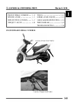
Страница 3: ...ial Number 1 ENGINE FRAME SERIAL NUMBER 1 ENGINE SERIAL NUMBER 1 0 TOOLS 1 11 SPECIFICATION 1 1 LUBRICATION POINTS 1 12 SERVICE PRECAUTIONS 1 2 CABLE HARNESS ROUTING 1 14 TORQUE VALUES 1 10 WIRE DIAGR...

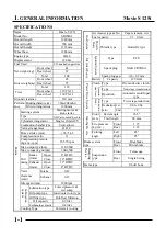
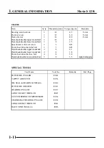
Страница 4: ...Exhaust Open 32 BTDC 1mm Close 4 BTDC Valve Intake 0 12 clearance cold Exhaust 0 12 Idle speed rpm 1800 rpm Lubrication type Forced pressure wet sump Oil pump type Inner outer rotor type Oil filter ty...

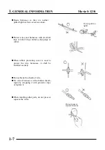
Страница 5: ...ghtening bolts or nuts begin with larger diameter to smaller ones at several times and tighten to the specified torque diagonally Use genuine parts and lubricants When servicing the motorcycle be sure...

Страница 6: ...he mutual working safety Disconnect the battery negative terminal before operation When using a spanner or other tools make sure not to damage the motorcycle surface After operation check all connecti...

Страница 7: ...pecified capacity After operation terminal caps shall be installed securely When taking out the connector the lock on the connector shall be released before operation Hold the connector body when conn...

Страница 8: ...ged terminal cover or loose negative terminal Check the double connector cover for proper coverage and installation Insert the terminal completely Check the terminal cover for proper coverage Do not m...

Страница 9: ...make sure that it is not interfering with any moving or sliding parts When fixing the wire harnesses do not make it contact the parts which will generate high heat Route wire harnesses to avoid sharp...

Страница 10: ...ontact a sharp edge or corner When rubber protecting cover is used to protect the wire harnesses it shall be installed securely Do not break the sheath of wire If a wire or harness is with a broken sh...

Страница 11: ...ositions When a testing device is used make sure to understand the operating methods thoroughly and operate according to the operating instructions Be careful not to drop any parts When rust is found...

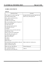
Страница 12: ...ent the servicing methods and cautions included in this service manual Apply engine oil to the specified points Use designated engine oil for lubrication Apply grease for lubrication Transmission Gear...

Страница 13: ...s Cylinder head bolt A Cylinder head bolt B Oil filter screen cap Exhaust muffler joint lock nut Cylinder head nut Valve adjusting lock nut Cam chain tensioner slipper bolt Oil bolt Clutch outer nut C...

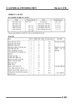
Страница 14: ...hock absorber lower mount bolt Front shock absorber hex bolt Rearshockabsorberlowerjointlocknut 1 1 1 1 1 1 1 2 2 4 1 10 12 14 10 8 5 5 8 8 8 8 4 5 6 0 11 0 4 0 2 5 0 45 0 45 0 1 1 8 3 0 3 5 U nut U n...

Страница 15: ...necting rod big end Crankshaft Crankshaft one way clutch movable part Oil pump drive chain Starter reduction gear engaging part Countershaft gear engaging part Final gear engaging part Bearing movable...

Страница 16: ...nd movable parts not specified This will avoid abnormal noise and rise the durability of the scooter Seat Lock Rear Wheel Bearings Grease Front Brake Cable Speedometer Cable Throttle Cable Main Stand...

Страница 17: ...1 GENERAL INFORMATION Movie S 125i 1 14...

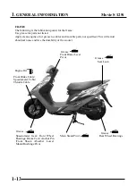
Страница 18: ...vie S 125i 1 15 CABLE HARNESS ROUTING Brake Fluid Reservoir Rear Brake Cable Regulator Rectifier Tilt Switch Seat Lock Cable Fuel Filler Cap Lock Cable Separator Breather Hose Horn Wink Relay Ignition...

Страница 19: ...NERAL INFORMATION Movie S 125i 1 16 Ignition Switch Fuel Filler Cap Wire Harness Front Brake Hose Fuel Overflow Hose Fuel Tank Fuel Pump Separator Breather Hose Fuel Filler Cap Lock Cable Seat Lock Ca...

Страница 20: ...vie S 125i 1 17 Fuel Tube Spark Plug Cap Vacuum Tube Fuel Injector Throttle Body TPS Air Bypass Valve Secondary Air Cleaner Starter Motor Temperature Manifold Absolute Pressure Sensor Throttle Cable E...

Страница 21: ...RAL INFORMATION Movie S 125i 1 18 Exhaust Pipe Battery Fuel Tank Fuel Pump Fuel Unit Throttle Body TPS Diagnostic connector ECU Fuel Injector O2 sensor connector Ignition Coil Fuse set Secondary Air C...

Страница 22: ...1 GENERAL INFORMATION Movie S 125i 1 19 Fuel Unit ABV Starter Relay Battery T MAP sensor ECU Fuel Pump Fuel Tank Fuel Tube Secondary Air Cleaner Fuel Injector Fuel Tube...

Страница 23: ...1 GENERAL INFORMATION Movie S 125i 1 20 WIRING DIAGRAM...

Страница 24: ...ECU Good spark Broken or shorted spark plug wire Faulty ignition switch Faulty ignition pulse generator Loose or disconnected spark plug wire 5 Test cylinder compression Low compression Valve stuck o...

Страница 25: ...leaner dirty not increase Restricted fuel flow Clogged muffler Engine speed increase Pinched fuel tank breather 4 Check ignition timing Incorrect Faulty ECU Faulty ignition pulse generator Correct 5 T...

Страница 26: ...rol orifice Valve train lubricated properly 11 Check for engine overheating Overheating Fan motor not working Excessive carbon build up in combustion chamber Use of poor quality fuel Not overheating W...

Страница 27: ...regulator Normal 3 Inspect the fuel injector Abnormal Faulty injector Normal 4 Check for leaks in the intake pipe Leaking Loose insulator clamp Damage insulator No leak 5 Perform spark test Weak or in...

Страница 28: ...Camshaft not installed properly Correct 5 Check valve spring Weak Faulty valve spring Not weak POOR HANDLING Possible cause 1 If steering is heavy Steering stem adjusting nut too tight Damaged steeri...

Страница 29: ...em by force because the cover joint claws maybedamaged MakesuretoroutecablesandharnessesaccordingtotheCable HarnessRouting 2 0 2 1 2 4 TORQUE VALUES Exhaust muffler lock bolt 3 5 kg m Exhaust muffler...

Страница 30: ...EMOVAL Removefourscrewsattachingtotherearcareer Removetherearcareer REAR CAREER REMOVAL Removefourboltsattachingtotheluggagebox Removethescrewonthecenterluggage LUGGAGE BOX REMOVAL Be careful not to d...

Страница 31: ...er Be careful not to damage the claw while removing thefrontcentercover Remove four plastic screws attaching to the front bottomcover Removethefrontbottomcover 2 EXHAUST MUFFLER FRAME COVER 2 2 Screw...

Страница 32: ...ng to the back of front handlebarcover Remove the bolt attaching to the front of front handlebarcover Installationisinthereverseorderofremoval Removefourboltsontothefloorboard Removethefloorboard Inst...

Страница 33: ...COVER REMOVAL EXHAUST MUFFLER RemovethewireofO2sensor Removetwoexhaustmufflerjointbolts Removethreeexhaustmufflerlockbolts Removethepackingattachedtheexhaustmuffler When installation first install th...

Страница 34: ...AIR CLEANER SPARK PLUG VALVE CLEARANCE CYLINDER COMPRESSION FINAL REDUCTION GEAR OIL 3 7 DRIVE BELT BRAKE SYSTEM STEERING HANDLEBAR HEADLIGHT AIM 3 8 CLUTCH SHOE WEAR 3 8 SUSPENSION 3 8 WHEEL TIRES M...

Страница 35: ...12 Rear 3 INSPECTION ADJUSTMENT CHASSIS Rear brake free play 10 20mm TORQUE VALUES Front axle nut 4 5 kg m Rear axle nut 8 10 kg m 130 70 12 1 Rider Front Rear 1 75 kg cm2 1 75 kg cm2 2 00 kg cm2 2 25...

Страница 36: ...lean CVT at every 2000 km 3 INSPECTION ADJUSTMENT Regular Service Mileage km Frequency Item 300 1000 3000 4000 5000 6000 7000 8000 9000 10000 11000 12000 Engine Oil R New R R R R R R Engine Oil Filter...

Страница 37: ...adjustment of the throttle grip free play is made with the adjusting nut at the throttle body side Adjust by loosening the lock nut and turning theadjustingnut Minor adjustment is made with the adjus...

Страница 38: ...it is excessively dirtyordamaged MAINTAIN INTERVAL More frequent replacement is required when riding inunusuallydustyorrainyareas Air filter Spark plug SPARK PLUG Removethesparkplugcapandsparkplug Ch...

Страница 39: ...ck nut and adjust by turning the adjustingnut Valve Wrench CYLINDER COMPRESSION Warmuptheenginebeforecompressiontest Removethecentercoverandluggagebox Removethesparkplug Insertacompressiongauge Open t...

Страница 40: ...ondition Sealing washer Oil drain bolt GEAR OIL CHANGE Removetheoilcheckbolt Remove the oil drain bolt and drain the oil thoroughly Installtheoildrainbolt Torque 1 0kg m Fill the final reduction with...

Страница 41: ...lebar upright and check if the front brake fluid level is at the upper limit If the brakefluidisinsufficient filltotheupperlimit SpecifiedBrakeFluid DOT 4 The brake fluid level will decrease if the br...

Страница 42: ...ight aimadjustingbolt CLUTCH SHOE WEAR Start engine and check the clutch operation by increasingtheenginespeedgradually If the motorcycle tends to creep or the engine stop check the clutch shoes for w...

Страница 43: ...ts for looseness Tighten them to their specified torque values if any loosenessisfound WHEELS TIRES Check the tires for cuts imbedded nails or other damages Checkthetirepressure Tire pressure should b...

Страница 44: ...4 4 LUBRICATION SYSTEM 4 0 SERVICE INFORMATION 4 1 TROUBLESHOOTING ENGINE OIL OIL FILTER OIL PUMP 4 4 4 LUBRICATION SYSTEM Rocket arm shaft Crankshaft Oil pump Oil filter screen 1 3 Movie S 125i...

Страница 45: ...it reaches its servicelimit Aftertheoilpumpisinstalled checkeachpartforoilleaks SPECIFICATIONS 0 12 0 12 0 2 0 05 0 10 Standard mm Service limit mm Inner rotor to outer rotor clearance Outer rotor to...

Страница 46: ...GE The engine oil will drain more easily while the engineiswarm Remove the oil filter screen cap located on the bottom of the engine to drain the engine oil thoroughly Oil filter screen cap After the...

Страница 47: ...er bolts and the rightcrankcasecover Removethegasketanddowelpins Removethestarteridlegearandstarterclutch Removethetwoboltsandoilseparatorcover 4 3 4 LUBRICATION SYSTEM REMOVAL Bolts CPS A C Generator...

Страница 48: ...disassembletheoilpump INSPECTION Measurethepumpbody to outerrotorclearance ServiceLimit 0 12mm Measuretheinnerrotor to outerrotorclearance ServiceLimit 0 12mm 4 LUBRICATION SYSTEM 4 4 Screw DISASSEMBL...

Страница 49: ...4 LUBRICATION SYSTEM 4 5 Insert the pump shaft by aligning the flat ontheshaft withtheflatintheinnerrotor Outer rotor Inner rotor Dowel Pins Pump cover Installthedowelpin Install the pump cover by ali...

Страница 50: ...driven gear with the cutout in thepumpshaft Installandtightenthepumpdrivengearnut Torque 1 0kg m Installtheoilseparatorcoverandtightenthebolts 4 LUBRICATION SYSTEM 4 6 Oil pump Dowel Pins Dowel Pins S...

Страница 51: ...Install the right crankcase cover and tighten the ninebolts Torque 0 9kg m 4 LUBRICATION SYSTEM 4 7 Right crankcase cover CPS Bolts A C Generator Diagonallytightentheboltsin2 3times Movie S 125i...

Страница 52: ...CELP 5 5 HOW TO SHOW THE FAILURE CODE 5 6 DTC CODES LIST 5 7 SYNERJECT M3A ECU MODULE 5 11 ECU MODULE 5 13 TO INITIAL TPS AND ABV 5 15 FUEL PUMP T MAP SENSOR 5 17 TPS ENGINE TEMPERATURE SENSOR 5 18 F...

Страница 53: ...5 Fi INJECTION SYSTEM MOVIES125i 5 1 SYSTEM DIAGRAM O2 CPS T MAP TPS WTS O2 Voltage INJECTOR ABV KEY OFF INDUCTIVE IGNITION COIL ECU FUEL PUMP KEY ON ROLL...

Страница 54: ...5 Fi INJECTION SYSTEM MOVIES125i 5 2 Fi PARTS DRAWING...

Страница 55: ...re sensor resistance 11 15K 7 45 25 C Throttle position sensor voltage Idle 0 0 23 0 05V Throttle fully 90 3 27V Fuel pump resistance 20 C 68 F F about 7 3 E about 95 5 O2 sensor heater resistance 6 7...

Страница 56: ...or performance drive ability and poor Faulty fuel pump operating system fuel economy Clogged fuel filter fuel pump Pinched or clogged fuel hose Clogged fuel injector Faulty fuel injector Faulty spark...

Страница 57: ...There are three kinds of priority grade let user to know what kind of trouble was happened z Priority grade 1 CELP blinks continuously This is the most emergent situation like engine over heat User s...

Страница 58: ...code and then show the other higher number one after four seconds All the failure codes would be shown repeatedly How To Reset Failure Code z After repairing the trouble you should clear the failure c...

Страница 59: ...alfunction 2 1 Check if the connector of crankshaft position sensor is loosen 2 Check if the Rotor is align with Crankshaft position sensor during the crankshaft running 3 P1120 Throttle position sens...

Страница 60: ...ture sensor or electric circuit malfunction 2 1 Check if the connector of Inlet air temperature sensor loosen 2 Check if the resistance of sensor is normal 8 P0410 Idle air valve or electric circuit m...

Страница 61: ...han top speed 2 Check if the belt of CVT is broken 14 P1560 Sensor don t receive power source from ECU 2 1 Check if ECU output DC5V to sensor 2 Check if the power source of all sensor is DC5V 3 Replac...

Страница 62: ...n 22 P1110 Roll sensor or electric circuit malfunction 2 1 Check if the sensor installation direction is correct 2 Check if voltage of sensor is fit in specification 3 Check if ECU pin is broken 23 P0...

Страница 63: ...le before switching off 2 Removing luggage box and fixed bolts of battery terminals remove terminal first then terminal 3 To push the stopper and release the pulling rod of ECU module coupler Rotate t...

Страница 64: ...rm if operating throttle smoothly and throttle back in position precisely when release acceleration 5 Proceeding TPS initial and adaptation setting after replacing the ECU module would be necessary 6...

Страница 65: ...he TPS s knob of ECU set to axle of throttle body then assemble the ECU module tightening four fixed screws evenly with specific torque 0 3 0 37 kgf m and install to vehicle 4 Connecting diagnostic to...

Страница 66: ...coupler to ECU module notice its direction 3 To press the top of coupler with the finger and rotate the pulling rod by thumb at the same time in the meantime bumps of ECU seat should be engaged with t...

Страница 67: ...de the diagnostic cable To ground the initial terminal to battery terminal or frame ground by an additional wire that will succeed in initialing TPS and ABV value which recorded in ECU ECU module and...

Страница 68: ...range 0 23 0 05V and the variations in those five values should be 0 03 V 2 Accelerating a bit that means opening the throttle around 10 and then full close the throttle at least five times then recor...

Страница 69: ...ce of the fuel pump to see if it is short circuit or not T MAP Manifold Air Temperature Pressure Sensor To connect the PDA or KYMCO Fi diagnostic tool Enter the Data Analyze item to check if the manif...

Страница 70: ...dle 0 0 23 0 05V Throttle fully 90 3 27V ENGINE TEMPERATURE SENSOR Removal Remove the throttle body Dismantle the intake manifold Disconnect the connector of engine temperature sensor Remove the engin...

Страница 71: ...sensor s wires Standard 8 24 14 4K Torque 60 90 kg cm INJECTOR Inspection Measure the resistance of the Injector Standard 20 C 68 F 10 6 15 9 ECU Bolt Injector Replace a new O ring and lubricate with...

Страница 72: ...2 The level of detergent solution in the ultrasound tank shall not exceed the height of wiring receptacle of fuel injector 3 Inject detergent at the inlet port of fuel injector and clean for 30 minute...

Страница 73: ...sor heater two white wire pins Standard 20 C 68 F 6 7 9 5 Connect the PDA or KYMCO Fi diagnostic tool Choose the Data Analyze Check Page 05 Key switch ON then start engine till O2 heater activation is...

Страница 74: ...hould be stopped running when the vehicle inclines over 65 for safety When you place the vehicle back to normal situation you have to key off and key on the switch then it can be restarted Standard No...

Страница 75: ...rottle body or engine overhauled the efficiency of air intake would be changed have to do the TPI ABV initialization process When the engine is started turn off the ignition switch first and then turn...

Страница 76: ...le kPa 48 60 kpa Injection duration ms 1 6 2 6 ms Ign Advance 30 200 BTDC Ign Dwell duration ms 2 0 2 2 ms Air Temp C environ temp 2 C Engine Temp C 110 0 C IDLE CO 1 8 2 8 COFPC ABVAngDurMech 140 Eng...

Страница 77: ...ation Instructions Part No 3620A LEB2 E00 10 9 8 7 13 6 5 4 3 KEY FUNCTION 1 Model No 2 DownButton 3 DTC indicator Failure codes 4 Enter or Exit 5 Power indicator 6 UPButton 7 Adjust TPIandABVresetfun...

Страница 78: ...agnostic tool with the connector of harness wire located beside the Battery Diagnostic Tool Connector Pressthe Enter button Check the software version Press the Enter button and then turn to the first...

Страница 79: ...25i Press the Enter button tocheck the DTC number Pressthe Enter button Pressthe Enter button Display what s DTC number on this DTC List Refer to DTC summary list Press the Enter button and then turn...

Страница 80: ...5 Fi INJECTION SYSTEM MOVIE S 125i Pressthe UP button Press the Enter button and then turn to the previous page Pressthe UP button Press the Enter button and then turn to the first page 5 28 LGH6...

Страница 81: ...JECTION SYSTEM MOVIE S 125i DTC CLEAR PROCEDURE Choose Load DTC Pressthe Down button Pressthe Enter button The DTC indicator is lighting at that time Clearing DTC completed until the DTC indicatorisof...

Страница 82: ...specifications Pressthe Down buttontoenterpage02 The figure includesTPS position TPI idle adapted voltage andTPIWOTadapted Throttle grip fully opened Refer to standard specifications Pressthe Down bu...

Страница 83: ...Down buttontoenterpage05 Thefigureincludes O2sensorvoltage O2 heater working condition and O2 correction Refer to standard specifications Pressthe Down buttontoenterpage06 The figure includes rollover...

Страница 84: ...nging new ECU and clean THROTTLE BODY and changing the engine department product let ECU set up and set up initially Choose Adjust Pressthe Enter buttontoTPI ABVReset Pressthe Enter button Please key...

Страница 85: ...6 0 6 6 ENGINE REMOVAL INSTALLATION Movie S 125i...

Страница 86: ...ONS The engine removal operation is required to support the engine Be careful not to damage the motorcyclebody cablesandwiresduringengineremoval Useshoptowelstoprotectthemotorcyclebodyduringengineremo...

Страница 87: ...rter relay Removethesparkplugcap Removetheignitioncoil swire RemovetheO2sensorwire Removetheboltattachingtotherearsuspension Removetheinjector swire Removethethrottlecable Removethevacuumtube Removeth...

Страница 88: ...Remove the engine mounting bolt and pull out the enginewiththeenginehangerbracketbackward 6 3 Removetheenginehangerbracketboltandnut Removetheenginehangerbracket 6 ENGINE REMOVAL INSTALLATION Brake A...

Страница 89: ...ctandadjustthefollowing Throttlegripfreeplay Rearbrakeadjustment 6 4 ENGINE HANGER BRACKET INSTALLATION 6 ENGINE REMOVAL INSTALLATION Bushings Stopper Rubbers Axle Engine Hanger Bracket ENGINE INSTALL...

Страница 90: ...7 0 7 7 CYLINDER HEAD VALVES Movie S 125i...

Страница 91: ...oval mark and arrange the removed parts in order When assembling install them in the reverseorderofremoval 7 CYLINDER HEAD VALVES 15 kg cm 570 rpm SPECIFICATIONS Item Standard mm Valve clearance cold...

Страница 92: ...ectvalvetiming 4 Brokenvalvespring 5 Valveseatleak 6 Leakingcylinderheadgasket 7 Warpedorcrackedcylinderhead 8 Poorlyinstalledsparkplug Compressiontoohigh Excessive carbon build up in combustion chamb...

Страница 93: ...o that the T mark on the flywheel aligns with the index mark on the crankcase to bring the round hole on the camshaft gear facing up to the top dead center on thecompressionstroke 7 CYLINDER HEAD VALV...

Страница 94: ...angle bolt attaching to camshaftholder Removethefixplate 7 4 7 CYLINDER HEAD VALVES Bolt Fix plate Bolt with six angle inner Rocker Arm Shafts Take out the valve rocker arm shafts using a 5mm bolt Re...

Страница 95: ...one if thebearingsarenoisyorhaveexcessivewear If the valve rocker arm contact surface is worn check each cam lobe for wear or damage Service Limits IN 25 57mmreplaceifbelow EX 25 41mmreplaceifbelow B...

Страница 96: ...ecamshaft Removethecoolingfancover Removetheenginecoverboltsandscrews Separatetheenginecoverjointclaws MeasuretheI D ofeachvalverockerarm ServiceLimits IN 10 10mmreplaceifover EX 10 10mmreplaceifover...

Страница 97: ...l Pins Gasket Cam Chain Guide Remove the valve spring cotters retainers springs spring seats and valve stem seals using a valvespringcompressor CYLINDER HEAD DISASSEMBLY Be sure to compress the valve...

Страница 98: ...e areas for cracks Check the cylinder head for warpage with a straightedgeandfeelergauge ServiceLimit 0 05mmrepairorreplaceifover Valve Spark plug Valve Spring VALVE SPRING FREE LENGTH Measure the fre...

Страница 99: ...stallnewvalvestemseals Installthevalvespring Valve spring compressor E040 Special Valve spring compressor Tap the valve stems gently with a plastic hammer for2 3timestofirmlyseatthecotters Becarefulno...

Страница 100: ......

Страница 101: ......

Страница 102: ......

Страница 103: ......

Страница 104: ......

Страница 105: ......

Страница 106: ......

Страница 107: ......

Страница 108: ......

Страница 109: ...10 10 FINAL REDUCTION 10 0 Movie S 125i...

Страница 110: ...10 1 FINAL REDUCTION INSPECTION 10 2 140 cc 120 cc TROUBLESHOOTING FINAL REDUCTION DISASSEMBLY BEARING REPLACEMENT FINAL REDUCTION ASSEMBLY E014 TROUBLESHOOTING Engine starts but motorcycle won t move...

Страница 111: ...ankcasecover Removetheclutch drivenpulley Drain the transmission gear oil into a clean container Remove the transmission case cover attaching bolts Removethetransmissioncasecover Removethegasketanddow...

Страница 112: ...specttheoilsealforwearordamage Inspect the drive shaft and gear for wear or damage Check the transmission case cover bearings for excessive play and inspect the final shaftbearingoilsealforwearordamag...

Страница 113: ...ring driver Drive shaft Removethedriveshaft Removetheoil sealdriveshaft Remove the left crankcase bearing using a bearing puller Drivenewbearingsintotheleftcrankcase Installanewdriveshaft soilseal Ins...

Страница 114: ...resin washer onto the countershaft Install the dowel pins and a new gasket Tranmission case cover Install the transmission case cover Install and tighten the transmission case cover bolts Installthec...

Страница 115: ...ssion case with thespecifiedoil Place the motorcycle on its main stand on levelground Check the oil sealing washer for wear ordamage Specified gear oil SAE90 Oil Capacity At disassembly At change 140...

Страница 116: ...11 11 CRANKCASE CRANKSHAFT 11 0 Movie S 125i...

Страница 117: ...Connecting rod big end side clearance Connecting rod big end radial clearance Runout Crankshaft TORQUE VALUES Crankcase bolt 1 0 kg m Cam chain tensioner slipper bolt 1 0kg m SPECIAL TOOLS Oil seal B...

Страница 118: ...RANKCASE CRANKSHAFT Remove the cam chain tensioner slipper bolt and cam chain tensioner slipper Check if the O ring damaged Cam chain Cam Chain Tension Slipper Remove two bolts attaching to the right...

Страница 119: ...oil seal lip for wear or deterioration Theinstallationsequenceisthereverseof removal Connecting rod big end CRANKSHAFT INSPECTION Service limit 0 55 mm replace if over Measuretheconnectingrodbigendsid...

Страница 120: ...excessiveplay If they do not turn smoothly quietly or if they fit loosely in the crankshaft replace the crankshaft as aset Install the cam chain into the left crankcase CRANKCASE ASSEMBLY Dowel pins...

Страница 121: ...Tighten the crankcase attaching two bolts Torque 0 9 kg m 11 CRANKCASE CRANKSHAFT Installthecamchain Installthecamchaintensionslipper Bolt Bolt Slipper Cam chain Movie S 125i...

Страница 122: ..._______________________________________________________________ __________________________________________________________________________________ _____________________________________________________...

Страница 123: ...12 FRONT WHEEL BRAKE SUSPENSION 12 1 Movie S 125i...

Страница 124: ...system when filling it with brake fluid Brake fluid will damage painted surfaces and plastic parts When servicing the brake system use shop towels to cover and protect rubber plastic parts and coated...

Страница 125: ...front axle or uneven tire Poor brake performance Incorrectly adjusted brake Worn brake linings Contaminated brake lining surface Worn brake shoes at cam contacting area Worn brake drum Poorly connecte...

Страница 126: ...pull out the axle Remove the front wheel Remove the front brake disk INSPECTION Set the axle in V blocks and measure the runout using a dial gauge The actual runout is 1 2 of the total indicator read...

Страница 127: ...quietly or loose BEARING REPLACEMENT Remove the front wheel bearings and distance collar Bearing Puller 12 mm E020 Pack all bearing cavities with grease Drive in the left bearing Install the distance...

Страница 128: ...to the axle shaft Install the front wheel by aligning the brake panel groove with the front fork tab Insert the axle shaft Connect the speedometer cable and secure it with the screw Install and tight...

Страница 129: ...12 FRONT WHEEL BRAKE SUSPENSION 12 7 Movie S 125i...

Страница 130: ...tem BRAKE PAD DISK REPLACEMENT Remove the two bolts attaching the brake caliper Remove the brake caliper Compress the brake caliper seat and press down the fixed reed to take out the brake pads When o...

Страница 131: ...ut Service Limit 0 3 mm INSTALLATION Install the brake caliper and tighten the two bolts Torque 2 9 3 5 kg m Connect the brake fluid tube to the brake caliper and tighten the fluid tube bolt Torque 2...

Страница 132: ...ve the circlip Set the front shock absorber in a vise Remove the damper rod hex bolt and copper washer Pull out the front shock absorber tube Set the front shock absorber tube in a vise Remove the loc...

Страница 133: ...ending Oil seal damage or wear Measure the front shock absorber spring free length Service Limits 251 mm ASSEMBLY Install the damper spring onto the damper rod and then install them into the front sho...

Страница 134: ...th the hex bolt Torque 1 5 3 0 kg m Specified Oil SS 8 Oil Capacity 120 cc Install the circlip Install the dust boot INSTALLATION Install the front shock absorbers onto the steering stem Install and t...

Страница 135: ...r cylinder holder bolts to remove the brake master cylinder Remove the throttle seat screw and throttle grip Remove the throttle seat from the handlebar and disconnect the throttle cable from the thro...

Страница 136: ...e bottom cone race using a chisel Drive a new bottom cone race into place with a proper driver BALL RACE REPLACEMENT Drive out the top and bottom ball races Long Socket Wrench Be careful not to lose t...

Страница 137: ...9 steel balls on the bottom ball race Apply grease to the ball races and install the front fork Apply grease to the top cone race and install it Tighten the top cone race and then turn the steering st...

Страница 138: ...Movie S 125i HANDLEBAR INSTALLATION Install the handlebar onto the steering stem tube and then install and tighten the bolt Torque 4 0 5 0 kg m Install the front wheel Install the brake levers Install...

Страница 139: ...13 13 0 13 REAR WHEEL REAR BRAKE REAR SUSPENSION Movie S 125i...

Страница 140: ...Exhaust muffler joint lock nut Exhaust muffler lock bolt 11 kg m 4 kg m 2 5 kg m 1 2 kg m 3 5 kg m SERVICE INFORMATION GENERAL INSTRUCTIONS During servicing keep oil or grease off the brake drum and b...

Страница 141: ...Exhaust muffler lock bolt 3 5 kg m Remove the O2 sensor s wire connector Remove the exhaust muffler Remove the rear axle nut and the rear wheel Be careful prevent the O2 sensor from damagewhileremovi...

Страница 142: ...ASSEMBLY Remove the rear brake adjusting nut and disconnect the rear brake cable Remove the rear brakeshoes Remove the brake arm bolt to remove the brake arm wear indicator plate and felt seal Remove...

Страница 143: ...REMOVAL Remove the frame body cover Remove the air cleaner case Apply a few amount of engine oil to the felt seal andinstallitto thebrakecam Installthewearindicatorplateandbrakearm Install the brake a...

Страница 144: ...ON Install the rear shock absorber Install the rear shock absorber upper mount bolt and then the lower mount bolt Tighten the bolts Torque Upper Mount Bolt 4 0 kg m Lower Mount Bolt 2 5 kg m Install t...

Страница 145: ...14 BATTERY CHARGING SYSTEM A C GENERATOR 14 0 14 CHARGING SYSTEM DIARGRAM Movie S 125i AC Generator Regulator Rectifier Battery Fuse Ignition switch 15A 12V9AH...

Страница 146: ...schargebyitselfandshouldberechargedevery3months A new battery filled with electrolyte will generate voltage within a certain time and it should be rechargedwhenthecapacityisinsufficient Recharginganew...

Страница 147: ...Flywheel puller E002 Item Standard Capacity Model 12V YTX9 BS GTX9 BS Fully charged 13 1V Voltage 20 C Undercharged 12 3V Charging current STD 0 9A Battery Charging time STD 5 10hr Capacity 150 W 500...

Страница 148: ...nd band First disconnect the battery negative cable and then the positive cable Open the battery cover and disconnect the battery cables Measure the voltage between the battery terminals CHARGING Conn...

Страница 149: ...ith battery terminals Attach a tachometer to the engine Start the engine and gradually increase the engine speed to measure thelimitvoltageandcurrent If the limit voltage is not within the specified r...

Страница 150: ...n the wire harness terminals according to the following Y e l l o w R G Forward Reverse Forward Pass Black Volt Sensor IC Reverse Disconnect Connectthevoltmeterwithbatterywires Start the engine and gr...

Страница 151: ...r Removethefancover Cooling Fan Remove the cooling fan by removing the four coolingfanattachingbolts Holdtheflywheelwithanuniversalholder Removetheflywheelnut Universal holder E017 Special Remove the...

Страница 152: ...C generator wire connector Bolts Bolts Wire Set Plate RemovetheA C generatorwiresetplate RemovetheCPSbolts Remove theA C generator wire rubber sleeve and CPS INSTALLATION Flywheel Cooling fan Fan cove...

Страница 153: ...kg m Stator 0 9 kg m Connect the A C Generator Wire Connector Install the Wire Set Plate A C Generator Wire Connector Connect the A C generator wire connector Universal holder Woodruff Key Clean the t...

Страница 154: ...4 BATTERY CHARGING SYSTEM A C GENERATOR Install the fan cover Install the right side cover Cooling fan Universal holder E017 Special Install the cooling fan Torque 0 9 kg m Fan cover 14 9 Movie S 125i...

Страница 155: ...___________________________________ __________________________________________________________________________________ _________________________________________________________________________________...

Страница 156: ...18 IGNITION SYSTEM 15 1 DINK 200i 125 IGNITION SYSTEM LAYOUT ABV T MAP TPS ECU Spark plug Ignition switch AC Generator CPS...

Страница 157: ...15 IGNITION SYSTEM 15 2 Movie S 125i IGNITION CIRCUIT...

Страница 158: ...a slower engine starting speed as well as no spark at the spark plug Use of spark plug with improper heat range is the main cause of poor engine performance Check the ignition system according to the...

Страница 159: ...bolt and the ignition coil INSPECTION Measure the resistance of ignition primary coil Standard 0 55 0 75 20 AC GENERATOR CPS Remove the body covers Disconnect the ignition pulse generator connector M...

Страница 160: ......

Страница 161: ......

Страница 162: ...e S 125i Ignition switch Front brake switch Starter switch Rear brake switch Starter relay Battery Fuse Starter motor Starter motor Starter relay Starter switch Front brake switch Rear brake switch Ig...

Страница 163: ...6 2 16 STARTING SYSTEM TROUBLESHOOTING STARTER MOTOR The removal of starter motor can be accomplished with the engine installed For the starter clutch removal refer to chapter 4 SPECIAL TOOL STARTER C...

Страница 164: ...crews Motor Case Starter relay G Y STARTER RELAY PERFORMANCE INSPECTION Removethebodycover Turn the ignition switch ON and the starter relay is normal if you hear a click when the starter button is de...

Страница 165: ...ls that connect to the battery positive cable andthestartermotorcable Connect a fully charged battery across the starter relayyellow redandgreen yellowwireterminals Checkfor continuitybetweenthestarte...

Страница 166: ...age andreplaceifnecessary MeasurethestarterdrivegearI D Service Limit 32 06 mm replace if over Inspect the needle bearing for wear or damage and replaceifnecessary CLUTCH BODY DISASSEMBLY Remove the r...

Страница 167: ...le Gear Shaft Starter Idle Gear MeasurethestarteridlegearI D ServiceLimit 10 05mmreplaceifover MeasurethestarteridlegearshaftO D ServiceLimit 9 94mmreplaceifbelow Plunger Clutch Cover Spring Roller An...

Страница 168: ...d starter drivegearandtheninstallthemtotheclutchbody Installthestarterclutchontothecrankshaft Apply engine oil to the starter idle gear and shaft andtheninstallthem Hold the starter drive gear with th...

Страница 169: ......

Страница 170: ......

Страница 171: ......

Страница 172: ......

Страница 173: ......

Страница 174: ......

Страница 175: ......

Страница 176: ......

Страница 177: ...OLSYSTEM SCHEMATIC DRAWING 18 1 EVAPORATIVE CONTROL SYSTEM 18 2 TROUBLESHOOTING 18 2 SERVICE INFORMATION 18 3 PERGE CONTROL VALVE 18 4 P C V BLOW BY 18 5 CHARCOAL CANISTER 18 6 EMISSION CONTROL SYSTEM...

Страница 178: ...18 EVAPORATIVE EMISSIONCONTROLSYSTEM MovieS125i 18 1 SCHEMATIC DRAWING Fuel Tank Charcoal Canister Air Cleaner Throttle Body Fuel Injector Catalytic converter...

Страница 179: ...por in the charcoal canister is drawn into the engine for re burning Charcoal Canister Absorb and store the vaporized HC from the fuel tank and carburetor The vaporized HC is absorbed in the charcoal...

Страница 180: ...tallation Replace any damaged tube with a new one Make sure to tighten the connector of each tube securely TOOLS Vacuum pump Pressure pump SPECIFICATIONS Purge control valve vacuum pressure 45 mm Hg C...

Страница 181: ...hat goes to the air cleaner and apply vacuum pressure of 250mm Hg The specified vacuum must be maintained for one minute Replace the purge control valve with a new one if vacuum is not maintained Conn...

Страница 182: ...flow is not reached INSTALLATION 1 Install the purge control valve in the reverse order of removal 2 Route and reconnect the purge control valve tubes properly and securely P C V CRANKCASE BLOW BY RE...

Страница 183: ...e Then connect a hose to the canister Blow the hose with mouth The charcoal canister is normal if air can be blown into it If clogged replace it with a new one 2 Check the charcoal for cracks and repl...

Страница 184: ...to prevent dirt or dust from affecting the operation of the air injection cut off valve Air Injection Cut off Valve Prevent exhaust muffler noise and backfiring at sudden deceleration The air injecti...

Страница 185: ...Faulty air cut off valve 5 Leaking vacuum tube Exhaust muffler noise 1 Faulty air injection cut off valve 2 Broken vacuum tube 3 Faulty reed valve SERVICE INFORMATION GENERAL INSTRUCTIONS During opera...

Страница 186: ...values replace with a new one The flow should be at least 30 liter min when a vacuum of 250mm Hg is applied The flow should be at least 1 6 liter min when a vacuum of 320mm Hg is applied Check each co...

Страница 187: ...emove the frame center cover Disconnect the secondary air inlet tube connector Remove the reed valve cover and two secondary air outlet tube nuts Check the reed valve for cracks damage big clearance o...

Страница 188: ...c Tool Operation Instructions Part No 3620A LEB2 E00 KEY FUNCTION ModelNo DownButton DTCindicator Failurecodes EnterorExit Powerindicator UPButton COAdjust 3 3 4 4 5 5 6 6 7 7 8 8 9 9 10 10 DATAAnalyz...

Страница 189: ...tic Standard Specifications Diagnostic Standard Specifications 19 19 8 8 DTC Inspection Precedure DTC Inspection Precedure 19 19 2 2 19 19 5 5 19 19 6 6 DTC Clear Procedure DTC Clear Procedure Data An...

Страница 190: ...nnector of harnesswirelocatedbesidetheBattery 19 2 Diagnostic Tool Connector Pressthe Enter button Checkthesoftwareversion Press the Enter button and then turn to the first page Pressthe Down buttonto...

Страница 191: ...ecktheDTCnumber Pressthe Enter button Pressthe Enter button Displaywhat sDTCnumberonthisDTC List RefertoDTCsummarylistonchapter5 Press the Enter button and then turn to the previouspage 19 Fi DIAGNOST...

Страница 192: ...19 4 Pressthe UP button Press the Enter button and then turn to the previouspage Pressthe UP button Press the Enter button and then turn to the first page 19 Fi DIAGNOSTIC TOOL OPERATION Movie S 125i...

Страница 193: ...PROCEDURE Choose Load DTC 19 5 Pressthe Down button Pressthe Enter button TheDTCindicatorislightingatthattime Clearing DTC completed until the DTC indicator isoff 19 Fi DIAGNOSTIC TOOL OPERATION Movi...

Страница 194: ...ttontoenterpage02 The figure includes TPS position TPI idle adapted voltage and TPI WOT adapted Throttle grip fully opened Refertostandardspecificationsonpage19 8 Pressthe Down buttontoenterpage03 The...

Страница 195: ...ndition and ABV adaptation opening angle Refertostandardspecificationsonpage19 8 Pressthe Down buttontoenterpage06 The figure includes ECU counter hours Tilt voltageandIgnitionchargingtime Refertostan...

Страница 196: ...mulated eng run time hr EngineSpeed IDLE rpm 1800 100 rpm 80 MAPSample kPa 42 51 kpa Injection duration ms 2 5 3 5 ms 80 2 8ms 3 5ms Ign Advance 10 14 BTDC Ign Dwell duration ms 2 0 2 2 ms Air Temp C...

Отзывы: