Chapter 6 - SAT Measuring Range
45
106 V3.2
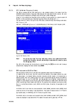
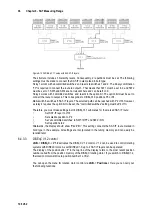
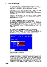
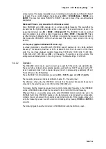
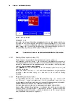
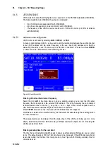
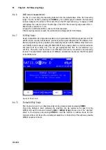
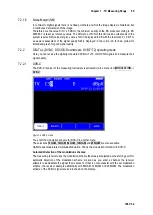
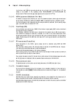
Figure 6-20 Antanna wall outlet configurator
Note:
With UNICABLE EN 50494 only the first 8 UB slots are addressable (see also
chapter 6.4.5 - JESS (EN 50607)).
An X represents a locked UB bandpass slot and a green check mark indicates an unlocked UB
slot. The current configuration is displayed in the “act.” line. This configuration can be determined
by selecting
Config. read
or edited by selecting
Config. write
. The “n-1” line displays the last
successfully programmed configuration, “n-2” displays the configuration previous to this, etc.
To change the current configuration, proceed as follows:
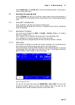
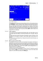
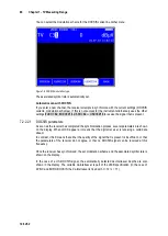
Select the “Config. write” menu using the up and down keys. Then press the → key to access the
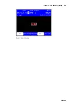
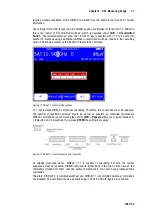
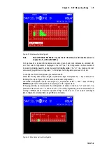
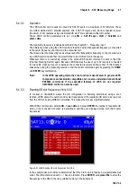
following menu (see Figure 6-21 Edit antenna wall outlet configuration).
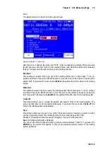
The desired configuration can be set using the ↑/↓ keys as well as the ← and → keys. Pressing
ENTER
programs this configuration and returns you to the original menu.
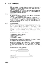
If the programming was successful, this configuration is shown in the lines “n-1” and “act.”, the
previous contents of line “n-1” is now in line “n-2”, etc. If the programming was not successful, the
message “DiSEqC answer incorrect” appears briefly and the lines n-1 to n-3 remain unchanged
(the configuration is transmitted using DiSEqC commands).
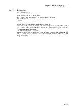
Figure 6-21 Edit antenna wall outlet configuration


