background image

KWE P

/N 542 0

19 Ve

rsatronik 

COMO OT V1

.1

 06/2009 Tec

hni

ca

l inform

at

io

subject to

 c

ha

nge

 without noti

ce 

Important Regulatory and Installation Requirements 

Codes 

The installation of this unit must 

be in accordance with local 
codes. 

 
All electrical wiring is to be done 

in accordance with the latest 
edition of CSA C22,1 Part 1 and/

or local codes. In the U.S. use 
the National Electrical Code 
ANSI/NFPA 70. 

 
The installing contractor must 

comply with the Standard of 
Controls and Safety Devices for 

Automatically fired Boilers, ANSI/
ASME CSD-1 where required by 

the authority having jurisdiction. 
 

Working on the equipment 

The installation, adjustment, 
service and maintenance of this 

unit must be done by a licensed 
professional heating contractor 

or persons who are qualified and 
experienced in the installation, 

service, and maintenance of 
similar products. There are no 
user serviceable parts on this 

control. 
 

Power supply 
Install power supply in 

accordance with the regulation of 
the authorities having jurisdiction 

or in absence of such 
requirements, in accordance with 
National Codes.  

→ 

Please carefully read this manual 
prior to attempting installation. 

Any warranty is null and void if 
these instructions are not 

followed. 


→ 

The completeness and 
functionality of field supplied 
electrical controls and 

components must be verified by 

those installing the device. 

!


WARNING 

More than one live circuit. See 

wiring diagram in this manual. 
Turn off power supply to control 

and damper/blower before 

servicing. Contact with live 

electrical components can result in 
serious injury or death 

Caution, Warning and Trademark Information 

Содержание Versatronik COMO OT

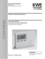
Страница 1: ...This is not a safety control Cautionary Statement Please observe the safety instructions and read through this manual carefully before commissioning the equipment IMPORTANT Read and save these instructions for future reference 1 2 47 Installation and Operating Manual ...

Страница 2: ...ion Section 1 Control Mounting and Installation Section 2 Boiler Control Wiring Overview Section 3 Mounting Wall Base and Room Controller Wiring Room Controller Outdoor temperature Sensor Connections Remote Telephone Switch Wiring Mode Selector Switch Menu Structure Overview Changing the Settings Expert Values Errors Start up and Commissioning Technical Data ...

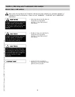
Страница 3: ...tuation which if not avoided could result in death serious injury or substantial product property damage CAUTION Indicates an imminently hazardous situation which if not avoided may result in minor injury or product property damage IMPORTANT Cautions draw your attention to the presence of potential hazards or important product information Helpful hints for installation operation or maintenance whi...

Страница 4: ...nsed professional heating contractor or persons who are qualified and experienced in the installation service and maintenance of similar products There are no user serviceable parts on this control Power supply Install power supply in accordance with the regulation of the authorities having jurisdiction or in absence of such requirements in accordance with National Codes Please carefully read this...

Страница 5: ... standards if the corresponding installation regulations and the manufacturer s instructions are complied with Please note the connection conditions specified by your local electrical power supply company and the VDE regulations Your heating control system may be installed and serviced only by appropriately authorized specialists E If the system is not installed properly there is a risk of fatal o...

Страница 6: ...6 KWE P N 542 019 Versatronik COMO OT V1 1 06 2009 Technical information subject to change without notice Section 1 This page is intentionally left blank ...

Страница 7: ...Control Installation Section 2 Control Installation Information Mounting Wall Base and Room Controller Section 2 0 Wiring Room Controller to Viessmann Vitodens 100 W WB1A Viessmann Vitodens 100 W WB1B Section 2 2 Outdoor temperature Sensor Connections Section 2 1 Remote Telephone Switch Wiring Section 2 3 ...

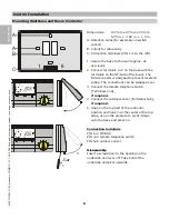
Страница 8: ...reversed poling The connections can be swapped over 3 Connect the remote telephone switch Terminals 3 4 if required 4 Connect the outdoor sensor Terminals 5 6 if required 5 Snap on the top part of the controller position and hook in at the center of the top edge use a little pressure to pivot it down onto the base and press on Connection terminals PIN 1 2 OT BUS PIN 3 4 remote telephone switch PIN...

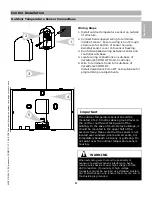
Страница 9: ...ersatronik Como OT onto sub base for programming or adjustments WARNING When extending wire there is the possibility of exposure to electromagnetic interference Avoid running wires beside or near high voltage 120 240 VAC conductors If proximity to high voltage conductors cannot be avoided use stranded twisted pair of shield design wire Ensure that only one end of the shielding is grounded Importan...

Страница 10: ...satronik COMO OT Room Controller 5 Locate wiring connections in sub base of Versatronik COMO OT Room Controller 6 Wire two wire communication wiring into terminals 1 and 2 of sub base Please note If the 4 pole plug referenced in step 2 is missing from the boiler please contact your Viessmann representative or wholesaler WARNING When extending wire there is the possibility of exposure to electromag...

Страница 11: ... wiring harness with the 6 pole terminal block attached 3 Locate the wire marker denoting terminal 1 4 If the outdoor temperature sensor has not been previously installed the outdoor temperature sensor can be wired to one of two locations It can be wired to the 6 pole connector from the boiler or directly to the Versatronik Como OT If wiring to the Como wall mounting plate connect to terminals 5 a...

Страница 12: ...ub base 3 Wire to terminals 3 and 4 WARNING When extending wire there is the possibility of exposure to electromagnetic interference Avoid running wires beside or near high voltage 120 240 VAC conductors If proximity to high voltage conductors cannot be avoided use stranded twisted pair of shield design wire Ensure that only one end of the shielding is grounded Wiring Steps 1 2 3 Important Ensure ...

Страница 13: ...xpert Values Overview of expert values Overview of code protected values Heating curve selection Explanation of settings Reset Section 3 4 Errors General error list Error 81 Other error numbers Communication with the boiler Unlocking the boiler Pump runs runs not Section 3 5 Section 3 0 Mode Selector Switch Normal Mode Party Key ECO Key Modifying the set room temperature Changing the Settings Sect...

Страница 14: ...Section 3 0 The slope adjustment operates in conjunction with the normal mode and reduced mode settings Adjustment of the heating slope is based on providing the heat necessary from the boiler system to overcome the heat loss of the structure By making adjustments to the slope and room temperature mode settings a boiler water temperature will be calculated Heating curve settings of 0 8 and below a...

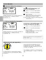
Страница 15: ...2 F Summer mode heating OFF only hot water preparation active h Day mode Normal mode 24 hour heating at comfort temperature 1 C Night mode Reduced mode 24 h heating at economy temperature Display in normal mode Due to inertia of the room temperature deviations of 1 C 2 F to the required room temperature are normal During transition from reduced operation and heating operation greater deviations ar...

Страница 16: ...3 sec the set extension of the heating time Heating at comfort temperature B Party key heating time extension Use to start setting display set extension of heating time press 1 hour for each actuation press 1 hour for each actuation press 3 seconds Heating circuit heats until the next day Display switches briefly to PARTY End the set PARTY function by pressing the Mode selector switch Modifying th...

Страница 17: ...s to select the level in which the value to be changed is located Overview on the following pages Ä Press the Prog key Open Select the level Use the Plus Minus keys to locate the value Overview on the following pages Ä Press the Prog key Select the value Warning triangle appears in the display Value can be changed Use the Plus Minus keys to change the value either Do not save the value ò Close the...

Страница 18: ... Time Date HTG PROG1 HTG PROG2 Expert Holiday HotWProg Expert Heatslope Adaption Room Infl1 I Control N Opt Time Max Opt Time Heat Up Opti User T Room Des1 T Room Des2 T Room Des3 T Reduced Max Modulati Max T HS T Absence Return C F HotWProg Display T Outside T Room T DHW T HS Burner Start Burner Time Modulation Return Water Press Time Date Adjust HTG Prog2 Adjust HTG Prog1 Adjust Time Day Time Se...

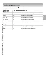
Страница 19: ... Operation Section 3 2 Main Menu Selections Page Reference Description User 18 Selection of base control settings Display 19 Review of current temperatures Time Day 20 Programming of time and day HTG Prog 1 21 Programming of timer programs HTG Prog 2 21 Programming of timer programs Hotwprog N A Holiday 23 Programming of holiday programs Expert 24 Programming of higher level settings ...

Страница 20: ...et room temperature for the night T ABSENCE 5o C 40o C 41o F 104o F 15C 59F T ABSENCE Set room temperature for the holiday period MAX T HS 30o C 110o C 86o F 230o F 85C 185F MAX T HS Maximum temperature of the boiler in heating operation Limitation for saving energy possible MAX MODULATI 0 100 80 MAX MODULATION Maximum modulation factor of the boiler in heating operation Output limitation of the b...

Страница 21: ...perature Min value with time Max value with time Ä RETURN T DHW T DHW Display of the current hot water temperature C F only in hot water tank mode Ä Current set temperature Ä RETURN T HS T HS Display of the current boiler temperature C F Ä Current set temperature Ä RETURN MODULATION MODULATION Display of the current boiler output 00 OF or value is not being sent BURNER TIME BURNER TIME Display of ...

Страница 22: ...ed by the value room sensor influence Usual value 30 min HEAT UP OPTI 0 1 0 Activate the function to automatically advance the start of the heating time MAX OPT TIME 0 3 2 00h Heating starts in advance maximally the amount of time set here N OPT TIME Display only Heating will start in advance today the amount of time set here T ROOM ADJUST 5o C 5o C 0 0o C 23o F 41o F 32o F Only with outdoor senso...

Страница 23: ...0o F 176o F 86o F RETURN Description Entry of code no Enter the correct code number to enable the following values to be changed Reselect a code number only with outdoor sensor When the outside temperature has dropped below the set limit value the heating circuit is switched on and set to the room temperature of 5 C 41o F The hot water temperature is set to 10 C 50o F The boiler is heated to the v...

Страница 24: ...control panel cover USER in the display 2x Plus key TIME DAY Ä Press the Prog key Time and E Use the Plus Minus keys to change the value Press and hold the key to scroll the value From the minute 00 15 30 or 45 in steps of 15 minutes Ä Press the Prog key Day and E Use the Plus Minus keys to change the value Ä Press the Prog key Save TIME DAY OPEN cover Î search for level using TIME DAY TIME WEDNES...

Страница 25: ...nday Ä Open weekday block see left I ON 20 C 68 F First switch on time set value I 20 C Set first switch on time for example 6 00 hrs Ä Confirm first switch on time I OFF 20 C 68 F First switch off time set value I 20 C 68 F Set first switch off time for example 8 00 hrs Ä Confirm first switch off time II ON 20 C 68 F First switch off time set value II 20 C 68 F Ä Switch on and switch off times 2 ...

Страница 26: ...00 to 22 00 Sa to Su 07 00 to 23 00 Heating program 2 Heating time 1 Heating time 2 Mo Tu We Th Fr Sa Su Heating time 3 Factory Setting Mo to Fr 05 00 to 21 00 Sa to Su 06 00 to 22 00 Factory Setting Mo to Fr 06 00 to 08 00 16 00 to 22 00 Sa to Su 07 00 to 23 00 Heating time 1 Heating time 2 Mo Tu We Th Fr Sa Su Heating time 3 Heating time 1 Heating time 2 Mo Tu We Th Fr Sa Su Heating time 3 Secti...

Страница 27: ...6x Plus key Display HOLIDAY and remaining days e g 00 Ä Prog key Display START HOLID and E Enter the number of days in which the holiday starts The start is always assumed at 12 00 pm Please do not enter the day of travel as the start date but the first day of the holiday no more heating from this day Ä Prog key Display HOLIDAY DUR and E Enter the duration of the holiday in days The end is always ...

Страница 28: ... 6 The adaptation is only activated at outside temperatures below 8 C 46 F and when the room temperature is below 18 C 64 F During the adaptation warm up of the living room begins after 3 hours at reduced operation nighttime Room temperature regulation is performed with a set value of 21 C 70 F As soon as the room temperature exceeds 20 C 68 F the room is regulated a further hour at 20 C 68 F The ...

Страница 29: ...he maximum time heating can be started in advance Required time advance This is the time the start of heating has been advanced for today display only Adaptation of room sensor This value can reduce the following disturbance variables for measuring the room temperature Production related deviation of the sensor Influence of the temperature of the room wall Operating temperature Outside temperature...

Страница 30: ...strument straightened paper clip Restart the equipment Ä Press Prog key and Reset button simultaneously release Reset button and keep Prog key pressed until EEPROM appears All set values are reset to their default values except heating programs and hot water program Restart Press Reset Load default settings Press Reset Prog Control Operation Section 3 4 ...

Страница 31: ...are to boiler manual 75 Outdoor sensor Check 80 Room sensor Check 81 EEPROM error Check set values Other error numbers Other error numbers may appear in the controller display as a result of the boiler Please refer to the boiler documents for their respective significance Pump runs runs not automatic Pump switching Switch off heating and pumps Room temperature Set temperature 1K Outdoor temperatur...

Страница 32: ...al carefully before starting up the equipment 2 Install the controller and switch on the boiler 3 Wait until the display appears in the operating unit 4 Wait until communication to the boiler is established 5 Set the language The first time the control panel cover is opened after switching on the power supply the language appears in the display It is only displayed once The language appears again ...

Страница 33: ...peration with set room temperature I When the short circuit is cleared heating resumes according to the set mode of operation or the set heating program The Versatronik COMO OT Room Temperature Controller can be programmed to allow full time operation in reduced mode Upon contact closure of the telephone input the room temperature set point is controlled by the normal room temperature settings Typ...

Страница 34: ...55 1823 120 C 248 F 194 1936 Control Operation Supply voltage OT 15 V DC with current limitation 13 mA Current consumption 5mA Type of protection complying to EN 60529 IP 40 Protection Class II complying to EN 60730 III Power reserve of the timer 10 hours Permitted ambient temperature during operation 0 to 50 C 32 to 122 F Permitted ambient temperature for storage 20 to 60 C 4 to 140 F Room sensor...

Страница 35: ...35 KWE P N 542 019 Versatronik COMO OT V1 1 06 2009 Technical information subject to change without notice Control Operation Notes Section 3 7 ...

Страница 36: ...atronik COMO OT V1 1 06 2009 Technical information subject to change without notice KWE Technologies Group 750 McMurray Road Waterloo Ontario Canada N2V 2G5 Tel 519 747 5042 Fax 519 747 4448 www kwe tech com info kwe tech com ...

Отзывы: