background image

Communica

tion 

Versatronik

®

502 & 502D 

Communication Gateway 
MODBUS 
 

Document Applicable to: 

Versatronik 502 & 502D NR2/Modbus 
Versatronik 502 NR2/MODBUS P/N 704087 
Versatronik 502D NR2/MODBUS P/N 704088 
 
Applicable Controls 
Vitocontrol-S, MW1 and MW2 
Vitotronic 300-K, MW1B and MW2B 
Vitotronic 100, GC1/GC1B 
Vitotronic 300, GW2 
Vitotronic 300, GW5B 
Vitotronic 200, HO1 
Vitodens 200 B2HA 

Technical, Installation and Configuration Information 

Cautionary Statement 
 
The information presented in this document is 
only to be used by those familiar with its 
application and use. 

IMPORTANT 

Read and save these instructions for 

future reference 

Содержание Versatronik 502

Страница 1: ...ntrols Vitocontrol S MW1 and MW2 Vitotronic 300 K MW1B and MW2B Vitotronic 100 GC1 GC1B Vitotronic 300 GW2 Vitotronic 300 GW5B Vitotronic 200 HO1 Vitodens 200 B2HA Technical Installation and Configuration Information Cautionary Statement The information presented in this document is only to be used by those familiar with its application and use IMPORTANT Read and save these instructions for future...

Страница 2: ...hich if not avoided may result in minor injury or product property damage IMPORTANT Cautions draw your attention to the presence of potential hazards or important product information Helpful hints for installation operation or maintenance which pertains to the product CAUTION Static sensitive components may be damaged by improper handling or work within the control Ensure all possible measures are...

Страница 3: ...ce and maintenance of similar products There are no user serviceable parts on this control Power supply Install power supply in accordance with the regulation of the authorities having jurisdiction or in absence of such requirements in accordance with National Codes Please carefully read this manual prior to attempting installation Any warranty is null and void if these instructions are not follow...

Страница 4: ...4 KWE P N 394046 Versatronik 502 and 502D MODBUS Gateway V1 0 Feb 2014 Technical information subject to change without notice Versatronik 502 This page is intentionally left blank ...

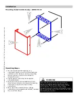
Страница 5: ...rews fasteners 3 Remove knockout and installed wire strain relief or box connector Removal of remaining knockouts is required to make further connections 4 Once all of the 120VAC and low voltage connections are complete and verified reinstall the cover from Step 1 When extending wire there is the possibility of exposure to electromagnetic interference Avoid running wires beside or near high voltag...

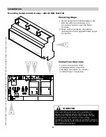
Страница 6: ...ections including the field supplied 24VAC power connection WARNING When extending wire there is the possibility of exposure to electromagnetic interference Avoid running wires beside or near high voltage 120 240 VAC conductors If proximity to high voltage conductors cannot be avoided use stranded twisted pair of shield design wire Ensure that only one end of the shielding is grounded Mounting Ste...

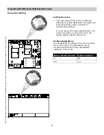
Страница 7: ...teways provides addressing information for systems that may utilize a number of Versatronik Gateways It is not required to make adjustments to the rotary dial setting It should be left in the factory default position setting of 0 Modbus Applications The Modbus device address can be set to either 88 or 1 through 9 The addressing can be accomplished with the rotary dial labelled Address on the PCB R...

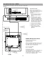
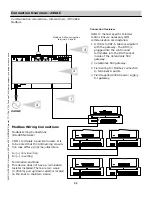
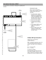
Страница 8: ...ateway 3 Versatronik 502 gateway 4 Modbus wiring connections 5 Plug in power cord for 120VAC Versatronik 502 gateways Connection Overview Connection Overview 120VAC Communication connections Vitotronic 100 GC1 or 300 GW2 Modbus 2 4 3 Modbus connections 120VAC 6 Modbus Wiring Connections RS 485 Network COM 1 terminals A and B are used It is to be noted that the A B naming convention may differ acro...

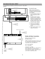
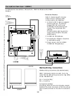
Страница 9: ...gateway The RJ45 is plugged into the control and terminates into the RJ45 socket inside of the Versatronik 502 gateway 3 Versatronik 502 gateway 4 Field wiring for Modbus connection to terminals A and B 5 Field supplied 24VAC power supply for gateway Connection Overview 2 4 3 Modbus Wiring Connections RS 485 Network COM 1 terminals A and B are used It is to be noted that the A B naming convention ...

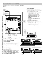
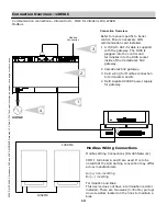
Страница 10: ... into the RJ45 socket inside of the Versatronik 502 gateway Vitocontrol S will need LON card installed 2 Versatronik 502 gateway 3 Field wiring for Modbus connection to terminals A and B 4 Plug in power cord for 120VAC Versatronik 502 gateways Connection Overview 1 2 Modbus Wiring Connections RS 485 Network COM 1 terminals A and B are used It is to be noted that the A B naming conven tion may diff...

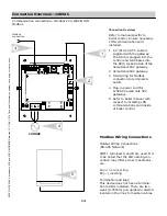
Страница 11: ...nto the control and terminates into the RJ45 socket inside of the Versatronik 502 gateway 2 Versatronik 502 gateway 3 Field wiring for Modbus connection to terminals A and B 4 Field supplied 24VAC power supply for gateway Connection Overview 1 3 2 Modbus Wiring Connections RS 485 Network COM 1 terminals A and B are used It is to be noted that the A B naming conven tion may differ across manufactur...

Страница 12: ...e RJ45 socket inside of the Versatronik 502 gateway Communication card required for Vitocontrol S MW2 for Vitodens WB2B boilers 2 Versatronik 502 gateway 3 Field wiring for Modbus connection to terminals A and B 4 Plug in power cord for 120VAC Versatronik 502 gateways Connection Overview 3 2 1 Modbus Wiring Connections RS 485 Network COM 1 terminals A and B are used It is to be noted that the A B ...

Страница 13: ...ed into the control and terminates into the RJ45 socket inside of the Versatronik 502 gateway 2 Versatronik 502 gateway 3 Field wiring for Modbus connection to terminals A and B 4 Field supplied 24VAC power supply for gateway Connection Overview 2 3 1 Modbus Wiring Connections RS 485 Network COM 1 terminals A and B are used It is to be noted that the A B naming convention may differ across manufac...

Страница 14: ...satronik 502 gateway 2 Versatronik 502 gateway 3 Field wiring for Modbus connection to terminals A and B 4 Plug in power cord for 120VAC Versatronik 502 gateways 5 Refer to boiler manual with respect to installing LON communications card inside of boiler control Connection Overview 2 1 3 5 Modbus Wiring Connections RS 485 Network COM 1 terminals A and B are used It is to be noted that the A B nami...

Страница 15: ...tronik 502 gateway 2 Versatronik 502 gateway 3 Field wiring for Modbus connection to terminals A and B 4 Field supplied 24VAC power supply for Versatronik gateway 5 Refer to boiler manual with respect to installing LON communications card inside of boiler control Connection Overview 5 1 2 3 Modbus Wiring Connections RS 485 Network COM 1 terminals A and B are used It is to be noted that the A B nam...

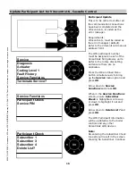
Страница 16: ...etting and ensure there are no duplicates Press the OK and lined Menu button simultaneously to bring up the Service menu option and press OK Arrow down to Service Functions and press OK When in the Service Functions screen ensure Subscriber Check is highlighted Arrow up or down to highlight if not and press OK Arrow down to Delete List and press OK The LON Participant information will be updated a...

Страница 17: ...seconds This will allow the Service screen to appear 2 With the arrow down button select the Service Functions menu option 3 Select Subscriber Check if not already highlighted and press OK 4 With the arrow up or down buttons select a subscriber and press OK The screen with show the check is active and will report back if it is okay or not 5 If the check was successful select a different user by us...

Страница 18: ...ration LED2 will blink every time a Modbus request is seen on the network Modbus Information Modbus Communication Configuration Settings The gateway is a Modbus slave and all communication has to be initiated by a master To set up successful communication with the gateway all connection parameters have to be set correctly to the following 9600 8 N 1 RTU Mode RTU Baud Rate 9600bps Data Bits Length ...

Страница 19: ...Boiler Zone A1 Writeable Curve Shift K Writeable 9 Zone Cascade Boiler Zone A1 Writeable Curve Slope 0 1 Res N A Writeable 10 Zone Cascade Boiler Zone A1 Writeable Curve Room Temp Normal C F Writeable 11 Zone Cascade Boiler Zone A1 Writeable Curve Room Temp Reduce C F Writeable 12 Zone Cascade Boiler Zone A1 Writeable Supply Set Point C F Writeable 13 Zone Cascade Boiler Zone M2 Writeable Curve Sh...

Страница 20: ...perature C F Read Only 40 Boiler 2 fault code Appendix A N A Read Only 41 Boiler 2 relay state Appendix B Unsigned Int N A Read Only 42 Boiler 3 actual temperature C F Read Only 43 Boiler 3 actual return temperature sensor 1 C F Read Only 44 Boiler 3 actual return temperature sensor 2 C F Read Only 45 Boiler 3 flue gas actual temperature C F Read Only 46 Boiler 3 fault code Appendix A N A Read Onl...

Страница 21: ...ead Only 68 Zone Cascade Boiler Zone M2 Curve Shift K Read Only 69 Zone Cascade Boiler Zone M2 Curve Slope 0 1 Resolution N A Read Only 70 Zone Cascade Boiler Zone M2 Curve Room Temp Normal C F Read Only 71 Zone Cascade Boiler Zone M2 Curve Room Temp Reduce C F Read Only 72 Zone Cascade Boiler Zone M3 Supply Set Point C F Read Only 73 Zone Cascade Boiler Zone M3 Supply Actual Temperature C F Read ...

Страница 22: ...temperature sensor 59 Interruption DHW tank temperature sensor 2 60 Short circuit return temperature sensor 17 68 Interruption return temperature sensor 17 70 Short circuit supply return temperature sensor 17B 78 Interruption supply return temperature sensor 17B 92 Solar collector temperature short circuit 93 Solar collector return temperature short circuit 94 Solar collector DHW tank temperature ...

Страница 23: ...circuit 2 dC Short circuit room temperature sensor heating circuit 3 dd Interruption room temperature sensor heating circuit 1 dE Interruption room temperature sensor heating circuit 2 dF Interruption room temperature sensor heating circuit 3 E0 Fault external participant device connected to LON Fault Code hex Description E4 Fault power supply voltage E5 Internal fault combustion control unit E6 F...

Страница 24: ... k k n 8 bit 28 Supply pump n n n k k k n n 9 bit 29 Primary pump heat exchanger set for DHW tank loading k k k n k k k n bit 29 DHW tank pump n n n n n n n k 10 bit 210 Boiler circuit and distribution common supply pump k k k n n n n k bit 210 Internal Pump n n n n n n k x 11 bit 211 Shunt pump k k k n n n n n bit 211 Diverting valve in space heating position n n n n n n n k 12 bit 212 Flue gas h...

Страница 25: ... between devices CAUTION Static sensitive components may be damaged by improper handling or work within the control Ensure all possible measures are taken to eliminate build up of static electricity 1 8 7 6 5 4 3 9 10 1 120VAC Power Supply Connections 3 Service Button 4 Modbus Connections to BMS 5 N A 6 N A 7 COM3 for multiple BUS connections 8 COM4 RJ45 Connection to control 2 Fuse 9 Power LED in...

Страница 26: ... between devices CAUTION Static sensitive components may be damaged by improper handling or work within the control Ensure all possible measures are taken to eliminate build up of static electricity 1 8 7 6 5 4 3 1 24VAC Power Supply Connections 3 N A 4 N A 5 COM4 RJ45 Connection to control 6 COM3 for multiple BUS connections 7 Service button 8 Service LED 2 Power LED indicator 9 Modbus Connection...

Страница 27: ...27 KWE P N 394046 Versatronik 502 and 502D MODBUS Gateway V1 0 Feb 2014 Technical information subject to change without notice Notes ...

Страница 28: ... and 502D MODBUS Gateway V1 0 Feb 2014 Technical information subject to change without notice KWE Technologies Group 750 McMurray Road Waterloo Ontario Canada N2V 2G5 Tel 519 747 5042 Fax 519 747 4448 www kwe tech com info kwe tech com ...

Отзывы: