background image

40

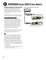
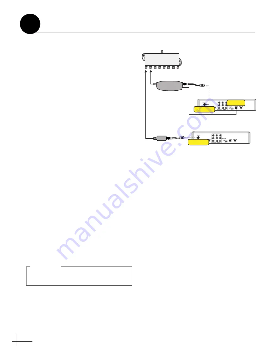
Additional Equipment for Older Receivers

In addition to the DECA Broadband Kit or a 
Genie DVR, you might need to connect an 
additional device in-line between the receiver 
and the SWM splitter, depending on the model 
(see Figure 67).

NOTE: 

Model HR20-100 requires additional devices 

not specified here. Contact KVH Technical Support.

H21, H22, H23, HR21, HR22, and HR23

These receivers do not have built-in DECA 
functionality, but they have an Ethernet port for 
network connectivity. An additional DECA 
(KVH part no. 19-0860) is required to support 
coax networking, supplying the satellite TV 
signal to the receiver's "Satellite In" port and 
network communications data to its Ethernet 
port. (If there are two of each port, use the 
"Satellite In 1" and "Ethernet 1" ports.)

NOTE: 

Each DECA you connect directly to a receiver 

is powered by the receiver. They do not require the 
separate power supply included in the kit. 

H20

This receiver is not network-ready. It is only 
designed to receive a satellite TV signal via its 
"Satellite In" port. Since both the satellite TV 
signal and network communications data are 
present on the coax cables, a band stop filter 
(KVH part no. 19-0868) is required to block the 
network data to prevent potential damage to the 
receiver. Since the H20 cannot communicate over 
the network, it cannot control satellite selection.

Figure 67:  Additional Equipment for Older Receivers

* Model HR20-100 may require additional hardware.
  Contact KVH Technical Support for details.

Satellite In

Old Receiver Models:

H21, H22, H23, HR21,
HR22, HR23

Satellite In

Old Receiver Models:

H20*

Ethernet

DECA

Band Stop Filter

SWM Splitter

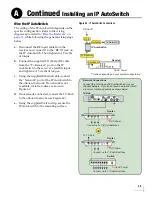
Be sure to connect all band stop filters before 

connecting the coax cables.

IMPORTANT!

Continued 

Using a DIRECTV Coax Network

B

Содержание TracVision TV5

Страница 1: ...KVH Industries Inc Installation Guide TracVision TV5 ...

Страница 2: ... the system To find a technician near you visit www kvh com wheretogetservice Technical Support If you need technical assistance please contact KVH Technical Support 1 Inspect Parts and Get Tools 3 2 Plan the Antenna Installation 4 3 Plan the TV Hub Installation 5 4 Prepare the Antenna Site 6 5 Prepare the RF Cables 7 6 Wire the Antenna 8 7 Remove the Shipping Restraint 9 8 Mount the Antenna 10 9 ...

Страница 3: ...ned KVH certified technician If you are a KVH certified technician you still must contact KVH Technical Support prior to conducting any repairs or modifications to the equipment WARNING Risk of Explosion Do not operate the TV Hub or any other electrical device in an environment where flammable gases vapors or dusts are present In addition do not operate the TV Hub in an environment with a temperat...

Страница 4: ...icone sealant or equivalent Satellite TV receiver s DVRs for your desired service see Figure 2 Wi Fi enabled laptop PC with the latest TracVision software and satellite library downloaded from the KVH Partner Portal www kvh com partners or Apple iOS or Android smartphone tablet with the latest downloads via the TracVision TV RV mobile app Always lift the antenna by the baseplate and never by the r...

Страница 5: ...location that is as close as possible to the intersection of the vessel s fore and aft centerline and midships Be sure to mount the antenna near enough to the TV Hub to allow you to connect the 100 ft 30 m coax cable between them while still maintaining sufficient slack in the cable NOTE If you need to use a longer cable use a RG 11 75 cable that does not exceed 200 ft 60 m in length see Prepare t...

Страница 6: ...tical mount to accommodate connecting the cables and making service loops within the proper bend radius If you plan to use the TV Hub s Wi Fi connections ensure the TV Hub mounting location provides adequate Wi Fi reception If you plan to connect the TV Hub to the vessel s onboard local area network LAN choose a location near an available Ethernet port NOTE A template showing the exact locations o...

Страница 7: ...ing hole locations you marked in Step b Later you will insert four 1 4 20 bolts through these holes to secure the antenna to the mounting surface d Cut out the 3 80 mm cable access hole in the location you marked in Step b Smooth the edges of the hole to protect the cables Later you will route the RF cable s through this hole and into the vessel e Clean and dry the antenna mounting surface f Peel ...

Страница 8: ... mm 0 064 1 63 mm dia 0 25 6 35 mm 0 5 12 7 mm 0 064 1 63 mm dia Figure 9 RF Cable Requirements Do not reuse old RF cables from a previous antenna installation The RF1 cable between the TV Hub and the antenna carries not only satellite signal but power and data as well Therefore the integrity and reliability of this cable is critically important RF cables must be rated for 75 not 50 Use of any cab...

Страница 9: ...e connector Then tighten it with a 7 16 torque wrench to 20 in lbs or a 7 16 wrench for 1 4 turn h Wipe off any excess grease from the outside of the connector i Repeat steps d h to connect any additional RF cables to the antenna s RF2 RF3 and RF4 connectors Later you will connect the RF1 cable to the TV Hub and any other RF cable s to a grounding block and receiver s j Seal the RF cable connectio...

Страница 10: ...adome on a hot steel deck the heat may warp the radome b Using a 10 mm socket wrench remove the bolt and spacer securing the antenna assembly to the baseplate see Figure 13 Save the restraint hardware for future use the customer will need to reinstall it if he she needs to relocate or reship the antenna 10 32 Screw x4 Figure 12 Removing the Radome Spacer Bolt Figure 13 Shipping Restraint Hardware ...

Страница 11: ...t on the baseplate are bottomed against the mounting surface and the foam seal is fully compressed e Reinstall the radome onto the antenna Secure in place with the four 10 32 screws you removed on page 9 Hide and protect the screws with the plastic screw caps supplied in the kit CAUTION Be sure to observe the safe handling instructions in the Material Safety Data Sheet MSDS provided with the anti ...

Страница 12: ...size gap to leave e Repeat step d on the other keyhole f Peel off the backing on the adhesive backed washer supplied in the kit and place it over the mounting tab hole see Figure 16 g Align the wide part of the TV Hub s keyholes as shown in Figure 17 over the screws then slide downwards to secure the screws into the narrow part of the keyholes h Press the rear mounting tab of the TV Hub onto the a...

Страница 13: ...o the Antenna jack Then tighten it with a 7 16 torque wrench to 15 in lbs or a 7 16 wrench 1 8 turn Deck Antenna To antenna only supplies 42 VDC RF1 Figure 18 TV Hub Antenna Connection Do not connect anything other than the antenna s RF1 cable to the Antenna jack The Antenna jack has 42 VDC on it which will damage other devices such as multiswitches DVRs etc IMPORTANT Wire the Antenna to the TV Hu...

Страница 14: ...ons Follow the steps in the applicable section below to wire the receivers Then connect the receiver s to the customer s television s Linear page 14 DIRECTV SWM page 16 DIRECTV Non SWM page 18 DIRECTV Latin America page 19 Tri Americas page 20 DISH Network Bell TV page 21 TV Hub A DIRECTV U S Non SWM Receivers DISH Network Bell TV and Linear Receivers DIRECTV U S SWM Receivers Figure 19 TV Hub A R...

Страница 15: ...her end of the RF1 cable to the Antenna jack on the TV Hub d Connect any other RF cables from the antenna RF2 RF3 and RF4 to the Satellite In jack on each additional receiver see Figure 22 Figure 21 Wiring 1 Linear Receiver TV Hub Antenna Receiver AC Power Satellite In Receiver RF1 TV Hub Antenna Receiver AC Power Satellite In Receiver RF1 Receiver AC Power Satellite In Receiver AC Power Satellite...

Страница 16: ...gure 23 and Grounding Requirements on page 23 c Connect the other end of the RF1 cable to the Antenna jack on the TV Hub d Connect the RF2 RF3 and RF4 cables to the multiswitch as shown in Figure 23 e Connect each multiswitch output to the Satellite In jack on each receiver f Terminate any unused outputs on the multiswitch with 75 terminators and verify all connections are tight Figure 23 Wiring 5...

Страница 17: ... SWM splitter with the supplied 75 terminators and verify all connections are tight Figure 24 Wiring 1 DIRECTV SWM Receiver TV Hub AC Power SWM Receiver Satellite In Antenna RF1 SWM Figure 25 Wiring a DIRECTV SWM Splitter TV Hub SWM R AUDIO OUT L Pr Pb Y VIDEO OUT S VIDEO OUT DIGITAL AUDIO OUT ETHERNET SATELLITE IN 1 IR RECEIVE SATA HDMI PHONE JACK POWER INPUT USB COMPONENT VIDEO OUT Genie DVR Gen...

Страница 18: ...DC Block Splitter Secondary Primary Secondary Primary SWM Power Inserter SWM 8 Module SWM1 PWR AC Power SWM Receiver DVR Satellite In Connect any combination of SWM receivers DVRs that add up to 8 or fewer tuners at the SWM splitter SWM Splitter Terminate unused outputs Supports up to 8 tuners Each SWM receiver 1 tuner Each SWM DVR 2 tuners IRD Legacy 2 Legacy 1 If you need to receive local channe...

Страница 19: ...k splitter to the 18V jack on the multiswitch and connect the Secondary jack on the DC block splitter to the 18V 22KHz jack on the multiswitch c Repeat steps a and b with Legacy 2 and the second DC block splitter using the 13V and 13V 22KHz jacks on the multiswitch d Connect the multiswitch outputs to the Satellite In jacks on the non SWM receivers e Terminate any unused outputs on the multiswitch...

Страница 20: ...it NOTE If you need to connect more than four receivers install a multiswitch that has more outputs KVH offers an 8 output multiswitch KVH part no 19 0573 d Set the power inserter s switch to the 17 18V HORZ 13 14V VERT position e Connect the Receiver jack on the TV Hub to the 13V jack on the multiswitch f Connect the multiswitch outputs to the Satellite In jacks on the receivers g Terminate any u...

Страница 21: ...DIRECTV U S receivers connect the external SWM 8 kit supplied in the kit to the multiswitch See Connecting 9 16 SWM Receivers or Tuners on page 17 for details f Terminate any unused connectors on the multiswitch and SWM splitter with 75 terminators and verify all connections are tight g For DIRECTV Latin America service set the tone generator switch to the ON position when using DIRECTV U S servic...

Страница 22: ...multiswitch see Figure 34 KVH offers a 4 output passive multiswitch KVH part no 72 0676 and an 8 output active multiswitch KVH part no 72 0677 d When using a multiswitch connect the multiswitch outputs to the Satellite In jacks on the receivers Receivers must be DISH Pro compatible Look for the DISH Pro logo on the box IMPORTANT Figure 32 Wiring 1 DISH Bell Receiver Receiver AC Power Satellite In ...

Страница 23: ...ne via a T connector as shown in Figure 35 Be sure to use a standard drop cable 5 wire 4 conductors shield twisted pair with micro C connectors b Configure the NMEA device to transmit one or more of the supported NMEA 2000 messages see Figure 37 Later you will select the NMEA source at the TracVision Setup Wizard see Setup Wizard on page 30 TV Hub OR B A 1 2 NMEA 0183 Talker NMEA 0183 NMEA 2000 Ta...

Страница 24: ...ount each grounding block using the two supplied 6 screws see Figure 38 WARNING Failure to ground the TracVision system properly to the vessel s ground will cause an unsafe floating ground condition risking damage to the antenna and electric shock potentially resulting in DEATH In a floating ground condition the difference between the equipment s chassis ground and the vessel s ground can measure ...

Страница 25: ...ub power cable supplied in the kit to the 10 30 VDC power input on the rear of the TV Hub c Connect the black wire of the TV Hub power cable to DC return ship s ground d Connect the red wire of the TV Hub power cable to the vessel s 12 VDC or 24 VDC power source 10 30 VDC is required at the TV Hub NOTE An optional 24 VDC AC DC power supply 5 A 120 W is available from KVH part no 72 0669 Ground DC ...

Страница 26: ... d Plug in and turn on any connected receivers DVRs Genie clients and televisions TV Hub Power Switch Figure 40 TV Hub Power Switch During startup the TV Hub checks the software versions installed in the antenna and updates them if necessary to match the versions it has stored for that model All three status lights see Figure 41 will alternate orange while this update is in progress Do not turn of...

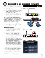
Страница 27: ...ub Using the Ethernet Connection a Connect a laptop PC configured for DHCP directly to the Ethernet port on the TV Hub see Figure 43 b Start your web browser and enter http 169 254 253 1 NOTE When connected to a vessel s LAN see Connect to an Onboard Network on page 27 you will need to enter the IP address dynamic or static assigned to the TV Hub If your laptop has Bonjour installed you can use it...

Страница 28: ...V Hub s Ethernet port is configured as a DHCP client and the network s router automatically assigns it an IP address However in this Dynamic mode the TV Hub could get assigned a different IP address whenever it is turned on KVH recommends that you set the TV Hub to Static mode and enter a static IP address at the web interface see Figure 46 go to Settings Network Settings Be sure to choose a stati...

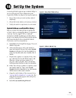
Страница 29: ...horized access to the TV Hub at the web interface go to Settings Network Settings If you keep the default settings you re allowing anyone to access the TV Hub with their mobile device Figure 47 TV Hub Security and Password Setting KVH strongly recommends that you keep the TV Hub set to AP Access Point wireless mode If you select IF Infrastructure mode to connect the TV Hub to your onboard network ...

Страница 30: ... The web interface appears b At the Updates page of the web interface select the antenna model Then select Install Update see Figure 49 Find the kvh file in your downloads folder then double click to install c Wait for the update to complete It may take up to 45 minutes The TV Hub s lights will alternate orange while the update is in progress Once complete the web interface will report that the la...

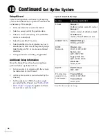
Страница 31: ...as Set up receivers to operate with the system as instructed by the Wizard Activate the receivers as instructed by the Wizard Set the antenna s LNB to the skew angle provided by the Wizard see Set the LNB Skew Angle on page 32 applies to linear manual skew systems only Figure 50 Preset Satellite Groups Note This list is subject to change Service Satellites A B C D Linear Europe 1 Hotbird Astra1 As...

Страница 32: ...e order as they were set up in the antenna The specific setup process varies among receiver models refer to the receiver s manual for details Use the table below and Figure 51 as a guide Satellites in Antenna Matching Satellites in Receiver Slot A Port Switch LNB DiSEqC 1 or A Slot B Port Switch LNB DiSEqC 2 or B Slot C Port Switch LNB DiSEqC 3 or C Slot D Port Switch LNB DiSEqC 4 or D Figure 51 L...

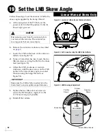
Страница 33: ...54 f Tighten the two M4 socket set screws to secure the LNB in place Apply 11 in lbs 1 2 N m of torque if possible g Reinstall the radome CAUTION Disconnect power from the antenna before you remove the radome The antenna has moving parts that can cause injury Figure 52 Location of LNB on Back of Antenna Reflector Reflector M4 Socket Set Screws Figure 53 Set Screws Securing the LNB to the Reflector...

Страница 34: ...ome protects the antenna s moving parts from wind rain and debris The antenna must have a clear view of the sky to receive satellite TV Common causes of blockage include trees buildings bridges and onboard equipment see Figure 57 Heavy rain or snow might also temporarily interrupt reception Clean the antenna regularly Dirt buildup on the radome can affect satellite TV reception You must be located...

Страница 35: ...othing was damaged in shipment c Locate the serial number on the bottom of the IP AutoSwitch see Figure 59 and record it on the Installation Checklist supplied in the Welcome Kit for future reference Choose a Mounting Location Choose a mounting location that meets the following requirements Dry well ventilated and away from heat sources Provides a clear view of and easy access to the Master Select...

Страница 36: ...ll a router as shown in Figure 60 d If not already connected connect the TV Hub to the onboard network see Figure 60 e Using the supplied Velcro strip secure the IP AutoSwitch to the mounting surface Connect up to 3 IP AutoSwitches 4 3 2 1 8 7 6 5 POE 48V Switch Network Connections Connect the TV Hub and IP AutoSwitch es to your onboard network If you do not have a network install a router or rout...

Страница 37: ...tion a To choose the master receiver select it on the Home page of the web interface or press the Master Select button on the associated IP AutoSwitch b Verify that the LED in the Master Select button on the IP AutoSwitch is lit green see Figure 62 The LEDs for any other IP AutoSwitches should be lit orange Figure 61 Add IP AutoSwitch Screen 140701234 The TV Hub has a built in IP AutoSwitch Any re...

Страница 38: ...er Receiver default setting The output of the TV Hub s Receiver port is the band and polarization that is currently selected by the master receiver This setting ensures the antenna always has a valid band polarization on which to track the satellite TV Hub The TV Hub ignores voltage tone from the master receiver and outputs whichever band polarization corresponds to the voltage tone that is presen...

Страница 39: ...coax cables This simplifies installation since Ethernet cables don t need to be run to all of the receivers Non Genie Configurations If a Genie DVR HR44 or HR34 is not present on the DIRECTV SWM network you need to install a DECA with power supply and DC to RF adapter collectively referred to as a DECA Broadband Kit KVH part no 19 0860 and formerly called a Cinema Connection Kit When connected to ...

Страница 40: ...e clients cannot switch satellites they can only view programming carried by the satellite that is currently selected Figure 66 Genie Configuration R AUDIO OUT L Pr Pb Y VIDEO OUT S VIDEO OUT DIGITAL AUDIO OUT ETHERNET SATELLITE IN 1 IR RECEIVE SATA HDMI PHONE JACK POWER INPUT USB COMPONENT VIDEO OUT Satellite In AC Power Ethernet Genie DVR HR34 or HR44 Genie Client Models C31 C41 Network New Rece...

Страница 41: ...A you connect directly to a receiver is powered by the receiver They do not require the separate power supply included in the kit H20 This receiver is not network ready It is only designed to receive a satellite TV signal via its Satellite In port Since both the satellite TV signal and network communications data are present on the coax cables a band stop filter KVH part no 19 0868 is required to ...

Страница 42: ...hing communications This IP address is not shown on the Network Settings page of the web interface Static IP Address Range WITH an Onboard Network If the TV Hub and the DECA Broadband Kit or Genie DVR are connected to an onboard network i e router set each receiver to a static IP address that is outside the router s DHCP range see Figure 69 Refer to the router s user manual for details on finding ...

Страница 43: ...c IP address On a Genie DVR the IP address is called the Server IP see Figure 70 f WITHOUT an Onboard Network Enter 255 255 255 0 for the subnet mask and enter the TV Hub s IP address for default gateway and DNS WITH an Onboard Network Enter the router s subnet mask and enter the router s IP address for default gateway and DNS g Highlight and select Connect Now to save your changes Disregard any e...

Страница 44: ... the Autoswitch Page Also be sure to set each receiver s Dish Type to 3 LNB and Switch Type to SWM and enable external device access as directed by the TV Hub s Setup Wizard If the TV Hub is then unable to communicate with the receiver try resetting the receiver press its red reset button or unplug it wait 15 seconds then plug it back in and turn it on IMPORTANT Continued Using a DIRECTV Coax Netw...

Страница 45: ......
Страница 46: ... 847 3327 Fax 1 401 849 0045 E mail info kvh com KVH Industries A S EMEA Headquarters Kokkedal Denmark Tel 45 45 160 180 Fax 45 45 160 181 E mail info emea kvh com KVH Industries Pte Ltd Asia Pacific Headquarters Singapore Tel 65 6513 0290 Fax 65 6472 3469 E mail info apac kvh com ...

Отзывы: