background image


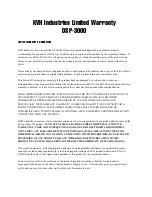
KVH Industries Limited Warranty 

DSP-3000 


LIMITED WARRANTY ON HARDWARE 

KVH Industries, Inc. warrants the KVH Fiber Optic Gyro purchased against defects in materials and 
workmanship for a period of ONE (1) year from the date of original retail purchase by the original purchaser.  If 
you discover a defect, KVH will, at its option, repair, replace or refund the purchase price of the product at no 
charge to you, provided you return it during the warranty period, transportation charges prepaid, to the factory 
direct. 

Please attach your name, address, telephone number, a description of the problem and a copy of the bill of sale or 
sales receipt as proof of date of original retail purchase, to each product returned to warranty service. 

This Limited Warranty does not apply if the product has been damaged by accident, abuse, misuse or 
misapplication or has been modified without the written permission of KVH; if any KVH serial number has been 
removed or defaced; or if any factory-sealed part of the system has been opened without authorization. 

THE EXPRESS WARRANTIES SET FORTH ABOVE ARE THE ONLY WARRANTIES GIVEN BY KVH 
WITH RESPECT TO ANY PRODUCT FURNISHED HEREUNDER; KVH MAKES NO OTHER 
WARRANTIES, EXPRESS, IMPLIED OR ARISING BY CUSTOM OR TRADE USAGE, AND 
SPECIFICALLY DISCLAIMS ANY WARRANTY OF MERCHANTABILITY OR OF FITNESS FOR A 
PARTICULAR PURPOSE.  SAID EXPRESS WARRANTIES SHALL NOT BE ENLARGED OR 
OTHERWISE AFFECTED BY TECHNICAL OR OTHER ADVICE OR SERVICE PROVIDED BY KVH IN 
CONNECTION WITH ANY PRODUCT. 

KVH’s liability in contract, tort or otherwise arising out of or in connection with any product shall not exceed the 
price paid for the product.  

IN NO EVENT SHALL KVH BE LIABLE FOR SPECIAL, PUNITIVE, 

INCIDENTAL, TORT OR CONSEQUENTIAL DAMAGES OR LOST PROFITS OR GOODWILL 

(INCLUDING ANY DAMAGES RESULTING FROM LOSS OF USE, DELAY IN DELIVERY OR 

OTHERWISE) ARISING OUT OF OR IN CONNECTION WITH THE PERFORMANCE OR USE OR 

POSSESSION OF ANY PRODUCT, OR ANY OTHER OBLIGATIONS RELATING TO THE 

PRODUCT, EVEN IF KVH HAS BEEN ADVISED OF THE POSSIBILITY OF SUCH DAMAGES. 

If any implied warranty, including implied warranties of merchantability and fitness for a particular purpose, 
cannot be excluded under applicable law, then such implied warranty shall be limited in duration to ONE (1) 
YEAR from the date of the original retail purchase of this product by the original purchaser. 

Some states do not allow the exclusion or limitation of implied warranties or liability for incidental or 
consequential damages, so the above limitations may not apply to you.  This warranty gives you specific legal 
rights, and you may also have other rights which vary from state to state. 


Содержание DSP-3000

Страница 1: ...DSP 3000 KVH DSP 3000 Fiber Optic Gyro Technical Manual ...

Страница 2: ...ng procedures product specifications or product use An electrical safety warning to help identify electrical issues that can be a hazard to either this KVH product or a user Information about installation maintenance troubleshooting or other mechanical issues Please direct questions comments or suggestions to KVH Industries Inc 50 Enterprise Center Middletown RI 02842 5279 USA Tel 1 401 847 3327 F...

Страница 3: ...KVH is a registered trademark of KVH Industries Inc ...

Страница 4: ...Wiring Guidelines 9 2 3 Preliminary Testing 10 2 3 1 Test Procedure 10 3 Digital 1000 Hz Asynchronous Interface 12 3 1 Description 12 3 1 1 Message Structure 13 3 1 2 Message Content 13 3 1 3 Message Rates 14 3 1 4 Synchronization 14 3 2 Wiring the Gyro for Digital Asynchronous Operation 15 3 2 1 Wiring Guidelines 15 3 3 Preliminary Testing 16 3 3 1 Test Procedure 16 4 Digital 1000 Hz Synchronous ...

Страница 5: ...2 4 3 1 Test Procedure 22 5 Analog Interface 24 5 1 Description 24 5 1 1 Analog Output Voltage Generation 24 5 1 2 Rate Scaling 24 5 2 Wiring the Gyro for Analog Operation 25 5 2 1 Wiring Guidelines 25 5 3 Preliminary Testing 27 5 3 1 Test Procedure 27 6 Mounting the Gyro 28 7 Troubleshooting 29 Appendix A Patent Protection 30 ...

Страница 6: ...uct Description The DSP 3000 is a single axis interferometric fiber optic gyro for use in a wide range of applications including antenna and optical stabilization navigation positioning aerospace AHRS IMUs robotics and instrumentation Based on proprietary polarization maintaining fiber and precision FOG technology the DSP 3000 employs a digital signal processor and an all fiber open loop optical c...

Страница 7: ...1σ of full scale Temperature Sensitivity 500 ppm 1σ 500 ppm 1σ Error full rate temp 1500 ppm 1σ 1000 ppm 1σ Bias Offset room temp 20 hr 100 hr Stability room temp 1 hr 1σ 3 hr 1σ Temperature Sensitivity 1 C min 6 hr 1σ 20 hr 1σ 40 Hz 100 Hz asynchronous Bandwidth 3 dB 400 Hz 1000 Hz synchronous or asynchronous 100 Hz 100 sec 100 Hz asynchronous Update Rate 1000 sec 1000 Hz synchronous or asynchron...

Страница 8: ... Incremental Angle or Integrated Angle Rate Physical Dimensions 3 5 x 2 3 x 1 3 88 9 mm x 58 42 mm x 33 02 mm Weight 0 6 lbs 0 27 kg Environmental Operating Temperature 40 F to 167 F 40 C to 75 C Storage Temperature 58 F to 185 F 50 C to 85 C Shock functional Functional sawtooth 40 g 6 10 msec Random Vibration 20 to 2000 Hz 8 g rms operational MTBF 55 000 hours ground mobile In all cases while ope...

Страница 9: ... C An interface control drawing ICD illustrating the dimensions connector placement and mounting holes is provided in Figure 1 All dimensions are shown in inches millimeters format Figure 1 Interface Control Drawing ...

Страница 10: ...face should be parallel to the plane normal to the rotational axis If this alignment is not observed the output data will vary as a function of the cosine of the misalignment angle 1 2 2 Interface Connector The DSP 3000 is equipped with a 15 pin interface connector of the following type Tyco Electronics single row Dualobe connector Tyco part number SSM015L2HN With the connector positioned at the t...

Страница 11: ... Gnd TTL Digital Ground 12 Tclk TTL Sync Serial Port Transmit Clock 13 Tdata TTL Sync Serial Port Transmit Data 14 Tsync TTL Sync Serial Port Transmit Frame Sync 15 Msync TTL Sync Serial Port Receive Frame Sync For a suitable mating connector use Tyco Electronics single row Dualobe plug assembly with flying leads Tyco part number SSL015PC2DCXXXN where XXX is length in inches This mating connector ...

Страница 12: ...II text consisting of two decimal data words separated by a space followed by a carriage return line feed sequence xxx xxxxxx y xxx xxxxxx Data Word 1 y Data Word 2 Output Data Word 1 Three user selectable formats Rate in degrees second the average over the interval from the last output this is the default mode at power up Incremental Angle in degrees the angular change from the last output Integr...

Страница 13: ... character User Commands Command Function R Switch output to Rate A Switch output to Incremental Angle P Switch output to Integrated Angle Z Zero the Integrated Angle value These single ASCII characters are input without a carriage return or line feed A command may need to be sent more than once for the command to execute ...

Страница 14: ...7 8 9 5 VDC RETURN DC SUPPLY COMPUTER COM PORT RX TX SIG GND 5 VDC POWER COMMON RX TX CASE GROUND SIGNAL COMMON 2 2 1 Wiring Guidelines Be sure to follow the guideline below to ensure optimum performance The chassis ground pin 3 as well as the housing should be coupled to the system ground with minimum impedance The surface on which the gyro is mounted should not inject AC noise onto the gyro hous...

Страница 15: ...1 Place the DSP 3000 module on a flat surface with the mounting surface down 2 Connect the 5 VDC 10 power supply positive to pin 1 connect the negative to pins 2 and 3 3 Connect the DB9 plug from the test cable harness to the computer s COM port Select the serial port to which the cable was connected open the test data acquisition program and select the following communications program settings 38...

Страница 16: ... output data should indicate a positive change 6 Slowly rotate the gyro in the opposite direction The output data should indicate a negative change 7 After the initial 5 second startup the BIT data word Data Word 2 should show ASCII 1 data valid at all times If the BIT shows ASCII 0 fault the gyro has malfunctioned ...

Страница 17: ...ow Control None The gyro s output has the following format Output Burst Rate 1000 second approximate see Note 1 Output Format Each character contains 10 bits 1 start bit Space binary 0 8 data bits 1 message byte starting with LSB 1 stop bit Mark binary 1 An idle line is always marking that is in a binary 1 state Four characters in sequence constitute a basic message Note 1 The output burst rate ma...

Страница 18: ...1 2 Message Content Note 1 Preset Bit 26 to 1 then compute Bit 26 Bit 0 Bit 1 Bit 2 Bit 25 Bit 26 Bit 27 Bit 28 Bit 29 Bit 30 Bit 31 Figure 5 Message Structure 3 1 2 Message Content Use of the 26 bit Content field depends on the Type bits as noted below Rate Data When the Type bits indicate Rate Data the contents are in two s complement format The LSB represents 60 µ s or 0 216 hr Incremental Angl...

Страница 19: ...Message 10 4th Message 11 This synchronization pattern allows you to design a receiver algorithm that can detect the first byte of a message For example you could create a state machine with two modes Acquisition and Locked In Acquisition mode the state machine would examine the sixth and seventh bits of each byte Once it finds a byte position that exhibits the defined synchronization pattern for ...

Страница 20: ... guideline below to ensure optimum performance The chassis ground pin 3 as well as the housing should be coupled to the system ground with minimum impedance The surface on which the gyro is mounted should not inject AC noise onto the gyro housing as it will radiate into the gyro electronics 1 2 3 4 5 6 7 8 9 10 11 12 13 14 15 1 2 3 4 5 6 7 8 9 5 VDC RETURN DC SUPPLY COMPUTER COM PORT RX SIG GND 5 ...

Страница 21: ...ce the DSP 3000 module on a flat surface with the mounting surface down 2 Connect the 5 VDC 10 power supply positive to pin 1 connect the negative to pins 2 and 3 3 Connect the DB9 plug from the test cable harness to the computer s COM port Select the serial port to which the cable was connected open your test data acquisition program and select the following communications program settings 115 20...

Страница 22: ...indicate a positive change 6 Slowly rotate the gyro in the opposite direction The output data should indicate a negative change 7 After the initial 5 second startup the Message Validity bit Bit 31 of the data message should show binary 1 data valid at all times If the Message Validity bit shows binary 0 fault the gyro has malfunctioned ...

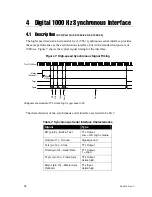
Страница 23: ...us Signal Timing The characteristics of the synchronous serial interface are listed in Table 7 Table 7 Synchronous Serial Interface Characteristics Signal Type BIT pin 8 Built in Test TTL Output Low OK High failure Gnd pin 11 Ground Signal ground Tclk pin 12 Clock TTL Output Tdata pin 13 Serial Data TTL Output 1 High Tsync pin 14 Frame Sync TTL Output Active high Msync pin 15 Master Sync Optional ...

Страница 24: ...one bit s time between messages When there is no message present on the interface the Frame Sync line is set to 0 The optional MSync input is a standard TTL clock input signal with a frequency equal to the gyro output rate The MSync signal should have a duty cycle of 40 60 and the frequency tolerance should be 100 ppm or better When the MSync signal becomes active high the data message shall begin...

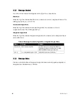
Страница 25: ...SB represents 6 µ Integrated Angle Data When the Type bits indicate Integrated Angle data the contents can be interpreted based on the table below Table 9 Message Contents Type Bits Integrated Angle Data Bit s Usage Values 25 24 23 360 modulo counter Increment when crossing from 359 to 0 Decrement when crossing from 0 to 359 Bit 25 is MSB Power up value is 0 22 0 0 integrated angle 360 LSB bit 0 v...

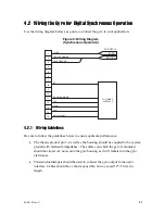
Страница 26: ...E SIGNAL COMMON Msync Optional 4 2 1 Wiring Guidelines Be sure to follow the guidelines below to ensure optimum performance The chassis ground pin 3 as well as the housing should be coupled to the system ground with minimum impedance The surface on which the gyro is mounted should not inject AC noise onto the gyro housing as it will radiate into the gyro electronics Twisted shielded pair should be...

Страница 27: ...rify proper unit operation and assist in troubleshooting Equipment needed to test the gyro 5 VDC power supply Interface cable with a female 15 pin single row Dualobe connector wired to your test application as shown in Figure 8 on page 21 4 3 1 Test Procedure Follow the steps below to test the gyro for proper operation 1 Place the DSP 3000 module on a flat surface with the mounting surface down 2 ...

Страница 28: ... Note Northern latitudes are positive and southern latitudes are negative 5 Grasp the gyro and slowly rotate it in the direction of the arrow on its serial number label The output data should indicate a positive change 6 Slowly rotate the gyro in the opposite direction The output data should indicate a negative change 7 After the initial 5 second startup the BIT indicator at gyro pin 8 should show...

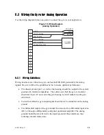
Страница 29: ... performance is optimized for this configuration there may be some reduction in performance from the digital gyro output The asynchronous output data rate remains at 100 Hz with a maximum gyro input rate of 375 second 5 1 1 Analog Output Voltage Generation As the gyro rate signal is digitally generated it must be converted to analog voltages in the gyro using a 16 bit digital to analog converter D...

Страница 30: ...to follow the guidelines below to ensure optimum performance The chassis ground pin 3 as well as the housing should be coupled to the system ground with minimum impedance The surface on which the gyro is mounted should not inject AC noise onto the gyro housing as it will radiate into the gyro electronics Current not related to gyro output signal should never be conducted on the analog ground The d...

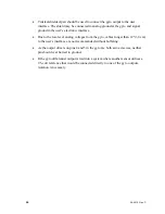
Страница 31: ...level analog voltages from the gyro cables longer than 12 30 cm to the user s interface are not recommended without buffering As the output drivers on pins 4 and 5 in the gyro are both active devices neither pin should ever be tied to ground If the gyro differential output is tied into a system where another sensor utilizes a 2 5 volt reference that would be connected directly to one of the gyro o...

Страница 32: ... Connect the 5 VDC 10 power supply positive to pin 1 connect the negative to pin 2 3 Connect the voltmeter across pins 4 positive and 5 negative of the gyro interface connector 4 Grasp the gyro and slowly rotate it in the direction of the arrow on its serial number label The voltage shown on the voltmeter should increase 5 Slowly rotate the gyro in the opposite direction The voltage shown on the v...

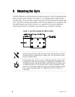
Страница 33: ...ound must be mechanically connected to the gyro housing for shielding Figure 11 Gyro Mounting Holes Bottom View Apply no greater than 8 in lbs of torque when securing the gyro to the mounting surface Tightening mounting screws any greater may affect the gyro s performance Performance of the gyro as a sensor is determined by the design of the mounting structure as well as the gyro s mechanical comp...

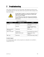
Страница 34: ...aged by misuse or as the result of service or modification other than by KVH Industries Table 10 Troubleshooting Symptom Possible Cause Action No DC power Check power measure power at the gyro No output Bad cable Check cable and terminal emulation setup no control signal BIT line level pin 8 is TTL High Internal fault Replace gyro Faulty ground Ground shield at gyro end only Erratic or low output ...

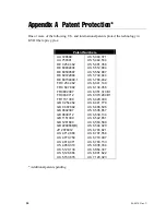
Страница 35: ... 0802397 GB 0838712 GB 1151309 GB 1261880 GB 2299668 B JP 2076012 US 4 712 866 US 4 773 759 US 4 818 071 US 4 950 318 US 5 120 130 US 5 126 666 US 5 153 676 US 5 340 371 US 5 444 534 US 5 481 358 US 5 512 904 US 5 552 887 US 5 739 944 US 5 768 462 US 6 041 149 US 6 134 356 US 6 351 310 B1 US 6 370 289 B1 US 6 429 939 US 6 441 779 US 6 466 596 US 6 535 657 US 6 539 134 US 6 542 651 US 6 563 589 US ...

Страница 36: ...STOM OR TRADE USAGE AND SPECIFICALLY DISCLAIMS ANY WARRANTY OF MERCHANTABILITY OR OF FITNESS FOR A PARTICULAR PURPOSE SAID EXPRESS WARRANTIES SHALL NOT BE ENLARGED OR OTHERWISE AFFECTED BY TECHNICAL OR OTHER ADVICE OR SERVICE PROVIDED BY KVH IN CONNECTION WITH ANY PRODUCT KVH s liability in contract tort or otherwise arising out of or in connection with any product shall not exceed the price paid ...

Страница 37: ...DSP3000_cover KVH Industries Inc 50 Enterprise Center Middletown RI 02842 5279 U S A KVH is a registered trademark of KVH Industries Inc ...

Отзывы: