background image

   How to Access to Bit Assemblies

3-33

KVAL Service Manual

How to Access to Bit Assemblies

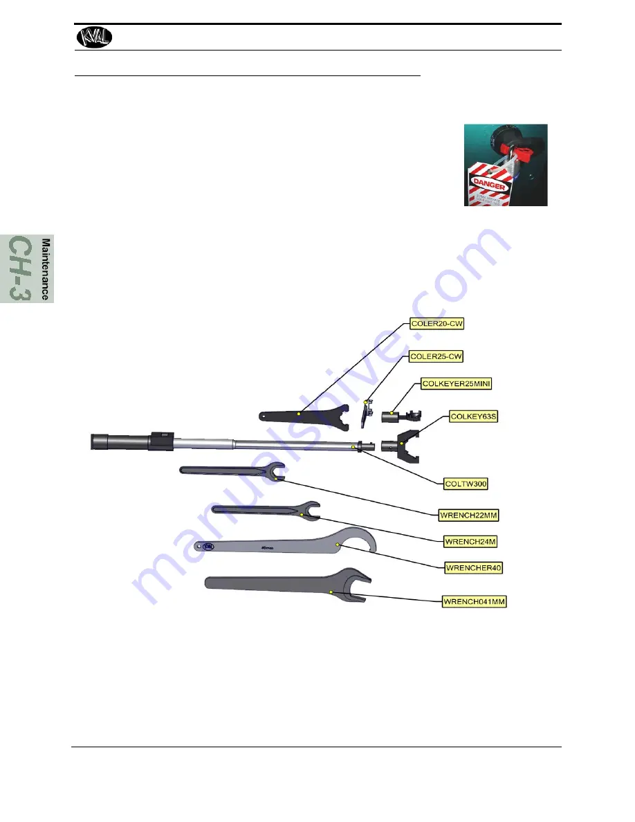
About the Tool Kit

A Tool Kit is provide with each machine. Kval recommends to torque the collet to the recom-
mended values. 

See “Collet Torque Values” on page 3-39 

Changing a Tool Bit and Using Tool-Change Tightening Fixture

The section describes how to change the bit in a tool, use the Tool-Change Tightening Fixture, 
and enter data into the 

Tool Setup Group.

This machine is a powerful electro-mechanical 
motion control system. If servicing this machine, fol-
low the safety guidelines. Failure to do so can result in 
damage to equipment and/or serious injury to person-
nel. Shutdown the machine and follow the 

“Lock Out 

Tag Out procedures.

Caution

Содержание EFX

Страница 1: ...Innovation Quality Honesty Service Manual Published March 2 2020 EFX Door Machining System Service Manual EFX System ...

Страница 2: ...istered trademark of Microsoft Corporation All other products are trademarks or registered trademarks of their respective holders all rights reserved Reference to these products is not intended to imply affiliation with or sponsorship of Kval Incorporated Contacting KVAL Customer Service For further information about this manual or other Kval Incorpo rated products contact the Customer Support Dep...

Страница 3: ...experience with our product that is the manual the machinery the software etc What was easy or difficult to use or to learn If you could change something about the design what would it be Please email your comments and suggestions for improve ment to userexperience kvalinc com NOTE This is not a customer support email link For that please refer to the Customer Service contact information above Tha...

Страница 4: ...KVAL EFX System Service Manual ...

Страница 5: ...the content generated through the KVALCAM Software are also the property of the Licensor and are protected by applicable law 1 Definitions a KVALCAM Software means the KVALCAM computer application installed in the KVAL Machinery and written documentation and materials provided to you as well as any revisions or updates of such computer application and documentation b Install means storing of the K...

Страница 6: ...KVAL EFX System Service Manual ...

Страница 7: ...ly 1 10 Start Maintenance 1 10 Post Maintenance Steps 1 10 Zero Energy to Start Up 1 11 Getting Help from KVAL 1 13 On Line Help 1 14 Product Return Procedure 1 14 How to Download the Service Application 1 15 Download Application 1 15 Safety Sign Off Sheet 1 18 A Note to the Operator 1 18 Chapter 2 System IT Administration System IT Administration 2 2 About the EFX Line Computer 2 2 Connections on...

Страница 8: ...te Slides Cylinder Rods and Bearing Shafts 3 11 72 000 Cycle Maintenance Steps 3 12 Inspect Nuts and Bolts 3 12 Check Door Feeding Transition If Applicable 3 12 Electrical 3 12 Computer Backup 3 12 Wash Filter and Lubricator Bowls 3 12 Maintenance NO GOES 3 13 Lubrication Schedule 3 14 Typical Lucubration Kit 3 14 Lubrication Requirements 3 15 Pillow Block Bearing Housings 3 15 Flange Bearing Hous...

Страница 9: ...Router or Pre Drill Bits 3 34 Replacing the Self Lubricator 3 36 Collet Torque Values 3 39 Chapter 4 Troubleshooting the EFX Line Troubleshooting Basics 4 2 Before you Adjust 4 2 Analyze the Sub Systems 4 4 About Motion Control 4 5 Sequencing 4 5 Point to Point 4 5 Incremental 4 5 Basic Control Circuit 4 6 About a Typical Contactor Control 4 7 About Contactor Troubleshooting 4 8 About Typical VFD ...

Страница 10: ...EFX 4 18 Network System Overview 4 19 Connections to Servo Drives 4 19 EFX Servo Motor Locations 4 20 About Switches and Sensors 4 21 Using Sensors to Trouble Shoot 4 22 About Checking the Revision Status 4 23 Troubleshooting Electrical Problems 4 24 If the Power Stops During Normal Operation 4 24 Description of the Light Tower 4 26 ...

Страница 11: ...Notes ...

Страница 12: ...rst IMPORTANT safety information is described in this section page 1 5 Lockout Tagout Guidelines Procedures describing Lockout Tagout page 1 9 Zero Energy to Start Up Procedure to power up your machine for the first time page 1 12 Getting Help from KVAL This section describes the method to con tact the KVAL Service Center for help The section includes how to get information from the specification ...

Страница 13: ... clamped for rail work The software automatically extends the correct door reference stop for positioning based on door swing end work or face work Edge detailing spindles are by Colombo and include a standard rotation 3HP reverse rotation 3HP 11HP deep mortise and 2HP drill spindle for screw pilot holes Four corner chisels are stan dard to square hinge pockets or lock face plates The entire edge ...

Страница 14: ...underneath the castor table two spindles are utilized for face routing to best suit individual cus tomer needs i e bit type the third 2HP spindle drill for lever lock screw holes Spindle movement is controlled via three additional ball screws and servo motors It is inde pendent of the edge detailing tower In operation the software will position the edge detailing tower an appropriate distance away...

Страница 15: ...t KvalCAM Descriptions of the KvalCAM user interface 3 Operation Inter face Descriptions of how to power machine line and operator inter face user screens 4 Calibration Descriptions of Calibration Rou tines and how to use the interfaces 5 Tour of the Machine Descriptions the assemblies on the machine Chapter Title Description 1 Introduction Safety Information 2 System IT Admin istration Descriptio...

Страница 16: ...r illegible There are three types of warning labels or decals DANGER means if the danger is not avoided it will cause death or serious injury WARNING means if the warning is not heeded it can cause death or serious injury CAUTION means if the precaution is not taken it may cause minor or moderate injury Safety Guidelines In addition to the caution and warning labels affixed to this machine follow ...

Страница 17: ...ver perform any maintenance unless machine is at zero state Never clean the machine while it is running Never walk away from the machine while it is running When the Machine is ON The compressed air system connected to this machine should have a three way air valve for shut off and pressure relief All cylinders on machine are under high pressure and can be very dangerous when activated Before perf...

Страница 18: ...t different locations Before performing any repairs or mainte nance lockout and tagout must be installed at all locations All maintenance and repairs to electrical circuitry should only be per formed by a qualified electrician Still has power in OFF position Electrical Prior to performing any maintenance repairs cleaning or when clearing jammed debris you must disconnect tag out or lock out the el...

Страница 19: ...you believe any part or operation of this machine is in violation of any health or safety regulation STOP pro duction It is your responsibility to immediately protect your employees against any such hazard Additional detailed safety guidelines are included in the operating instructions of this manual KVAL will be pleased to review with you any questions you may have regarding the safe operation of...

Страница 20: ...ag on each disconnect Only each operator may remove their own lock and tag Important When many people are all working on the same machine you will need a multiple lockout device such as the one shown here Follow the P R O P E R lockout rule of thumb P Process shutdown R Recognize energy type electrical pneumatic mechanical etc O OFF Shut off all power sources and isolating devices P Place lock and...

Страница 21: ...upply and pressure spring tension weight shifts etc 2 Inform all affected personnel of the eminent shutdown and the duration of the shutdown 3 Obtain locks keys and tags from your employer s lockout center 4 Turn off machine See Chapter 2 for power down and power up procedures 5 Turn the disconnect switches on ALL electrical and frequency panels to the OFF position Then push the red tab to pop it ...

Страница 22: ...ompletely removed and that all guards and safety devices are installed 10 Before removing the locks and tags the person who attached them shall inspect the equipment to ensure that the machine will not be put in an unsafe condition when re energized 11 The lock and tag can now be removed only by the person s who placed them and the machine can be re energized 12 The tags must be destroyed and the ...

Страница 23: ...n energy is restored Remove Locks Each operator must remove his or her own lock and tag This will ensure that all oper ators are in a safe place when the equipment is started Perform Visual Checks If the equipment is too large to see all around it station personnel around the area and sound the personnel alarm before starting the equipment If your operation is more complex your company s comprehen...

Страница 24: ...to your lock Proper lockout tagout can save lives limbs and money Help make your work environment safe for you and your fellow workers Be sure to follow the P R O P E R lockout tagout procedures and that those around you do also Close the Cage Gate Verify all cage gates are securely closed Ensure all safety protocols are in effect ...

Страница 25: ... the serial number 3 phase volts electrical print number and air print number 2 Contact our customer support team In the U S and Canada call 800 553 5825 or fax 707 762 0485 Outside the U S and Canada call 707 762 7367 or fax 707 762 0485 Email address is service KVALinc com Hours 6 00 AM to 4 00 PM Pacific Standard Time Monday through Thursday 6 30 AM to 1 30 PM Pacific Standard Time Friday Air D...

Страница 26: ... the following questions What is the extent of the failure reason for return What are the relevant error mes sages or error codes How long did it operate Did any other items fail at the same time What was happening when the unit failed e g installing the unit cycling power starting other equipment etc How was the product configured in detail Which if any cables were modified and how With what equi...

Страница 27: ...t the KVAL website select the Support tab Follow the instruc tions on the Support web page 3 Click the Download button to download the application that allows the KVAL technician to have access to the operator sta tion 4 After the download is com pleted double click the program icon Note Web browsers have different methods of downloading programs Below are samples of i e Explorer and Google web br...

Страница 28: ...am is ready to allow technicians to access machine computer Your Name Field Enter your name The KVAL techni cian will use this field to identify this machine Description Enter machine Serial number and issue Indicator Green indicates there is a good connection to the service center If red there could be an issue with a LAN connection Check the connections in the plant 7 After the KVAL Support App ...

Страница 29: ...How to Download the Service Application KVAL Service Manual 1 18 Page Intentionally Left Blank ...

Страница 30: ...y company s safety procedures I have read and understand these guidelines Machine Safety Concerns I have been given a tour of the machine and understand all the safety labels E Stops and the actions to take in case of an emergency I will make sure all guards are in place before operation I will turn off the compressed air before loading hardware staples screws etc I will turn off the electrical po...

Страница 31: ...Safety Sign Off Sheet KVAL Service Manual 1 20 ...

Страница 32: ...remotely help troubleshoot your machine Chapter 2 at a Glance Section Name Summary Page System IT Administration This section describes the basic parts of the operation of the PLC in the machine Such as About the PLC Connections on the PLC Backing up the Computer About Remote Connection to KVAL Service page 2 2 Updating Door Template Files This section describes the process of updating G code temp...

Страница 33: ... CPU module as a PLC Programmable Logic Controller In addi tion to the CPU and the chipset the module also contains internal main memory The computer has a removable Compact Flash card from which it boots Each controller utilize a Windows based operating system with TwinCAT 2 automation software to create the PLC and Motion Control method Interface modules include A smart power supply to connect t...

Страница 34: ...ection on the machine controller must have outside access to the Internet Exit Click to close the running Kval Cam program Backup Logs Click to save the to save all data from the machine operation Notes can be added to describe the saved file Backup and Export Click to send machine data to a text file The file may be sent to Service Support if any issues occur Notes may be added to describe the sa...

Страница 35: ...About Backing up the Data KVAL Service Manual 2 4 ...

Страница 36: ...es maintenance on the machine The maintenance is broken into machine cycle times and describes the sug gested maintenance steps to perform 300 Cycles 600 Cycles 3 000 Cycles 12 000 Cycles 72 000 Cycles page 3 2 Lubrication Requirements This section describes the lubrication require ments for the machine including types of lube to use This section includes Linear Bearings Flange Bearing and Pillow ...

Страница 37: ...may not pertain to all machines 300 Cycles Clean Use pressured air to blow off dust and debris on entire machine Clean Blow out dust collection cans 600 Cycles Inspect Air Pressure Gages Adjust if necessary to the proper PSI located on the label Adjust only if Trained in Maintenance Inspect Inspect Air Filter Water Traps Empty if necessary Inspect Inspect the Tooling for wear Drill Bits Cutting To...

Страница 38: ...pplicable Clean Clean all bearing shafts with clean dry cloth 12 000 Cycles Inspect Inspect chains for proper tension or damage Inspect Inspect all air cylinders for air leaks Replace if seal is leaking Inspect Inspect hydraulic lines for loose fittings leaks and cracks Inspect Inspect ball rail shafts for pitting or abrasions Lubricate Clean and lubricate all slides and cylinder rods with dry sil...

Страница 39: ... grime build up can cause issues with the operation of the machine Use pressured air to blow off dust and debris on entire machine Use a clean rag to clean areas not affected by pressurized air Also blow out any dust collection units Check vertical bearings for loose screws Loose screws could cause bearing damage High Dust Accumulation Areas ...

Страница 40: ...g Air Pressure Gages Adjust if nec essary to the proper PSI located on the label Adjust only if Trained in Maintenance Inspect Air Filter Water Traps Empty trap if necessary Slide locking switch down to unlock twist trap to remove Reverse action when installing trap Inspect the Tooling for wear Drill Bits Cutting Tools See How to Access to Bit Assemblies on page 3 33 ...

Страница 41: ...on the opera tor s station Empty Dust Collection Units Check and empty any dust collection units Clean any dust filters Dust collection systems vary from machine to machine Follow manufacturers directions to empty dust collection units FIGURE 3 2 Typical Dust Collection Unit Lift up and pull bottom out Remove screw and slide up Filters Dust Collection Con tainers ...

Страница 42: ... replace belt Belts can become slick from use lesson ing traction on door Check belts for slickness or door slippage Inspect all photo eyes secure and tight Check Connection to Photo Eye Check Nut that attaches Photo Eye to Machine Inspect all limit switch arms for tightness or breaks Inspect the switch for cracks in the body and check that the switch arm actuates clicking sound when moved to the ...

Страница 43: ...e connections assem blies air valves and hoses Check from source to end assembly Check Hoses for kinks and rubbing manifold con nections and Air Cylinder connections Ensure Air is turned off Refill all lubricators Replace fluid if milky or discolored Use ab ISO 32 stan dard hydraulic oil KVAL PN SYS LUBEG Slide locking switch down twist bowl and remove Refill bowl Reverse action when installing tr...

Страница 44: ...se ball screw bearings if applicable For a table of lubrication types to use Lubrication Schedule For locations to lubricate See Grease Ball Screw Bearings Clean Bearing Shafts Clean all bearing shafts with clean dry cloth Spray shaft with silicone oil and clean build up grime and dirt ...

Страница 45: ...ng Symptoms include a cylinder not extracting or retracting to the limits Cylinders not holding their position Inspect Hydraulic Lines If Applicable Inspect chains for proper tension or damage Check for sagging chains Chains can stretch over time of use Check for chain stiffness Stiff chains do not provide a tight fit over the gears Inspect hydraulic lines for loose fittings leaks and cracks Inspe...

Страница 46: ...ce Manual Inspect Ball Rail Shafts Clean and Lubricate Slides Cylinder Rods and Bearing Shafts Clean and lubricate all slides and cylinder rods with dry silicone spray Inspect ball rail shafts for pitting or abrasions Example of a Pitted Ball Rail ...

Страница 47: ...ions in each node box and electrical panel Wires may become loose due to vibration Check contactors for wear Computer Backup Backup computer software Wash Filter and Lubricator Bowls Check that there is a smooth transition with a door feeding into and out of machine Feed door in and out to verify smooth tran sition is repeatable Wash filter and lubricator bowls with soapy water Slide lock down to ...

Страница 48: ...ditions are changed timing accuracy or damage may occur during the machine process Do not adjust air PSI above or below factory settings Do not adjust any and all flow controls from factory settings Do not remove shim stock Do not Change or Alter any safety assemblies E Stops Gate Locks etc Do not Change programs in PLC s or PC s Do not Alter Electrical Components ...

Страница 49: ...ring Idler Shaft Flange Block Bearing Ball Screw Every 80 Hours of Machine Operation Tapered Bearing Once 4 X a Year Air Line Lubricator One drop of oil every 2 or 3 cycles Check the lines every week to two weeks Note Some CNC Machines drop every 5 10 cycles Either lubricant listed below is approved to use KVAL P N SYSLUBG Chevron AW Hydraulic Oil 32 G C lubricants light AW R O Mobile DTE 24 Shell...

Страница 50: ...ng is basically a valve that opens under pressure to allow lubricant to pass through a channel and be forced into the voids of the bearing When the pressure stops the ball returns to its closed position The ball excludes dirt and functions as a check valve to prevent grease escaping back out of the fitting The ball is almost flush with the surface of the fitting so that it can be wiped clean to re...

Страница 51: ...ble operation FIGURE 3 4 Flange Bearings Ball Rail Bearing Ball Rail Bearings are linear bearings that are attached to positioning rails In most cases the bear ings are attached to assemblies to move them in the X Y or Z direction FIGURE 3 5 Ball Rail Bearings Greasing Flange Bear ing Bearing Housings Approximatively 1 Gram one pump from grease gun of Dura Lith Grease KVAL P N Lube EP 2 Every 250 ...

Страница 52: ...n asset that the bearing blocks often require little maintenance for the life of the machine FIGURE 3 6 Sample of Tapered Bearing Tapered Bearing Housings The taper bearings differ from other machine bearing assemblies in that they are in a sealed envi ronment To identify a Tapered Bearing Housing look at the enclosure and verify there are seals between the screw and the housing FIGURE 3 7 Tapered...

Страница 53: ...all Nut Ball Screw Drive Assembly Including the Ball Screw Nut other types of bearings may be included on the assembly The figure below shows a typical Ball Screw Drive Assembly FIGURE 3 9 Ball Screw Drive Assembly Approximatively 1 Gram one pump from grease gun of Dura Lith Grease KVAL P N Lube EP 2 Every 80 hours of operation Ball Screw Nut Housing Ball Screw Drive Greasing Ball Screw Nut Servo ...

Страница 54: ...e door in and out of the machine Each pulley contains an idler shaft that has a zerk fitting to apply grease An opening in the idler shaft dispenses grease to the inner diameter of the pulley Pulley in Action Breakout of Pulley Assembly Grease IN Grease Out Note It is important not to overfill the Idler Shaft Avoid get ting excess grease on the belts Idler Shaft ...

Страница 55: ...n Schedule on page 3 14 FIGURE 3 10 Hub Bearing Locations This machine is a powerful electro mechanical motion control system If servicing this machine fol low the safety guidelines Failure to do so can result in damage to equipment and or serious injury to person nel Shutdown the machine and follow the Lock Out Tag Out procedures Caution Hubs 3 to 0 degree Tilt These bearings rarely need to be lu...

Страница 56: ... Rail Bearings on the Carriage Head To simplify the lubrication process divide the Carriage Head into 3 sections FIGURE 3 11 Carriage Head Sections Edge Cut Section Face Cut Section Stop and Probe Assembly Carriage X Axis 6 Bearings Rail is Lubricated by the WIT Applicator ...

Страница 57: ...arings in the Edge Cutting section are highlighted in the Figure below The Carriage assembly is divided into layers Find the X Y and Z bearings Identify zerk fittings and apply EP 2 grease Use an extender to reach tight areas FIGURE 3 12 Chisels Note Easy Access Zerk Fittings Located On Cover Plate 2 Bearings per Chisel Set Carriage Y Axis 4 Bearings Tool Set Z Axis 4 Bearings Tool Z Axis 2 to 4 B...

Страница 58: ... Make sure that Lockout Tagout has been performed before maintenance For lubrication sched ule information see Lubrication Schedule on page 3 14 Rail bearings in the Face Cutting section are highlighted in the Figure below FIGURE 3 13 Carriage X Axis 4 Bearings Tool Z Axis 2 Bearings per Motor ...

Страница 59: ...tify zerk fittings and apply EP 2 grease Use an extender to reach tight areas Make sure that Lockout Tagout has been performed before maintenance For lubrication schedule information see Lubrication Schedule on page 3 14 FIGURE 3 14 Grease Locations Probe Assembly X Axis 4 Bearings Vertical 4 Bearings ...

Страница 60: ...nce Assembly Lubrication Identify zerk fittings and apply EP 2 grease Use an extender to reach tight areas Make sure that Lockout Tagout has been performed before maintenance Each pop down gate has two bearings associated with the assembly Vertical 2 Bearings per Assembly ...

Страница 61: ...Z axis rails to identify bearings Some bearings may be difficult to get access to Use an extender to reach tight areas Make sure that Lockout Tagout has been performed before maintenance For recommended greasing sched ule see Ball Screw Drive Assembly on page 3 18 Face Cutter Z Axis Face Cutter Y Axis Edge Cutter Y Axis Edge Face Cutter X Axis Edge Cutter Z Axis ...

Страница 62: ...s the lubricated air to valve banks and air cylinders FIGURE 3 15 Typical Air Line Filter and Lubrication System Adjusting the Air Line Lubricator Using the knob on the top of the lubricator adjust until one drop per every other cycle is used as observed through sight glass Shop Air Input Air On Off Knob Muffler Filter purge Pressure Gauge with adjust Clean Dry Air CDA to Air Blow Off Lubricator L...

Страница 63: ...ny 32 To prime the lubricator find an air line on the carriage section of the machine that is energized and disconnect it allowing the air stream to bleed air pressure away from any persons Direct the air stream at the machine so you can see when there is an oily film blowing out of the air hose Repeat this same procedure for the back section and other trouble areas It is recommended to check the ...

Страница 64: ... 3 17 Tool Information Edge Cutter Motor Most CommonTool a a Most Common Tools Some bits may differ due to special cutting processes Collet Motor P N KVAL Collet Wrench PN KVAL Shaft Wrench PN 1 Chisels Sip013 N A N A N A N A 2 Drill JLD1563 COLER20 02 5 COLSE55E389 1 5 HP PERER20W WRENCH22MM 3 Router RS8855 COLER25 08 COLS73E478 3D 3 HP ER25 CW WRENCH24M 4 Router 5 Router RBSC1414800 Solid Carbid...

Страница 65: ... Tools Some bits may differ due to special cutting processes Collet Motor P N KVAL Collet Wrench PN KVAL Shaft Wrench PN 1 Router RS8855 COLER25 08 COLS73E478 3D 3 HP ER25 CW WRENCH24M 2 Drill JLD1563 COLER20 02 5 COLSE55E389 1 5 HP PERER20W WRENCH22MM 3 Router RS8855 COLER25 08 COLS73E478 3D 3 HP ER25 CW WRENCH24M Front ...

Страница 66: ...hisel Orientation on Machine Some machines have a rectangle orientation or a vertical orientation Below are samples of each Rectangle Orientation Lower Left Chisel Lower Right Chisel Upper Left Chisel Upper Right Chisel Vertical Orientation Sample is taken from a Face SS Sample is taken from an Edge SS ...

Страница 67: ...specially important for the lower tools where particulate can get trapped on the tool surface instead of falling under gravity s influence 6 Place the new chisel in the fixture add the clamp and tighten down the bolts back onto the clamp 7 Verify that the chisel does not wobble in the fixture after tightening Chisels should be rigid and straight in the assembly 8 Push the chisel cylinder back into...

Страница 68: ...ol Bit and Using Tool Change Tightening Fixture The section describes how to change the bit in a tool use the Tool Change Tightening Fixture and enter data into the Tool Setup Group This machine is a powerful electro mechanical motion control system If servicing this machine fol low the safety guidelines Failure to do so can result in damage to equipment and or serious injury to person nel Shutdow...

Страница 69: ...proper Lock out Tagout procedures as detailed in the safety section of Chapter 1 of this manual 2 Measure the parameters listed below Arbor Length The distance from the collet face to the tool s cutting edge Tool Length The distance from the collet face to the tip of the bit 3 Compare these measurements to the data in the Tool Setup Group in the Calibrate Machine Screen This screen is accessed by ...

Страница 70: ...bottom of the tool holder 6 Tighten the collet assembly 7 Inspect and verify the work Clean the work area 8 This is especially important for the lower tools where particulate can get trapped on the tool surface instead of falling under gravity s influence 9 Place the new chisel in the fixture add the clamp and tighten down the bolts back onto the clamp 10 Verify that the chisel does not wobble in ...

Страница 71: ...ronic and produces nitrogen gas in the well to increase pressure to push the oil out The lubricator well sends a replacement alert to the user screen when oil is low 5 The alert is a 30 day warning but it is recommended to change it as soon as possible Refer to Electrical Drawing for connections labels FIGURE 3 20 Location of Gear and Lubricator Electrical Connector Lubricator Well Sensor Hose Con...

Страница 72: ...y removing the grate below the heads 3 If needed cut the hose included in the kit to match the one on the machine 4 Attach the 2 hose connectors to the ends of the new hose 5 On the new lubricator well set the dip switches 6 Disconnect the black and red wires from the machine connector with a small screw driver Well Hose Sensor Hose Connectors Clamp Remove the protective top from lubri cator well ...

Страница 73: ... applicator 11 Bracket the new well against the machine 12 Slide the black and red wires into the connector Secure with a small screw driver 13 Polarity is not an issue but for consistency replace wires as they were 14 Route sensor wires to the corresponding node and connect to the correct terminals 15 After lubricator well is secured on machine perform a test run 16 Verify the oil is being applie...

Страница 74: ...ue Values 3 39 KVAL Service Manual Collet Torque Values KVAL recommends torquing the collets Torquing adds consistency is important for repeatable machining Follow the torque tool manufacturers method of torquing ...

Страница 75: ...Collet Torque Values KVAL Service Manual 3 40 ...

Страница 76: ...Notes ...

Страница 77: ... is available in this chapter Section Name Summary Page Troubleshooting Basics This section includes basic troubleshooting infor mation Includes analyzing sub systems to desig nate a starting point for troubleshooting page 4 2 About Motion Control This section contains basic information on the operation of motion control circuits Includes dia grams of the control circuits page 4 4 Describing Contr...

Страница 78: ...the router not cutting Is the cut out of specification Verify Verify or analyze the subsystem assembly that is responsible for the issue For example How is the subsystem supposed to work What is keeping the subsystem from working Before you Adjust Sometimes simple problems can seem to be complex issues Before making adjustments check for the following common issues 1 Is the loaded setup correct fo...

Страница 79: ...amp the Door Door Clamp 3 Make the Cuts Cutter Position ing Cutter Power 4 Unclamp the Door Door Clamp 5 Move Door Out Feed System 6 Wait for Next Door Feed System Basic Troubleshooting Steps Determine Where The Sequence Step Where the Failure Occurs What was the Machine Trying to Do What Was the Machine Trying to Do Next Check the Sequences in the Table Below How is the Broken Section Suppose to ...

Страница 80: ... are the correct photo eyes limit switches or ferrous sensors activated Check the con troller inputs to insure the proper sensors are activated If the controller is a PLC an activated input is lit Some touch screens have inputs status also 3 Common Position Feedback failures Photo Eye Bad element or bad cable Limit Switch Stuck or failure Wiring Broken worn insulation PLC Bad input port 4 Check th...

Страница 81: ... 6 Wait for the next door Point to Point Point to point motion control involves moving a load from one fixed position to another fixed position at a constant speed and along one line axis X Y or Z A typical point to point would be a drill with a fixed depth The drill is either retracted or extended using a pneumatic cylinder Typically the drills travel is limited by physical stops Incremental Incr...

Страница 82: ...en the humans and the machine Examples A touch screen a PC or a button panel The Controller Translates entered information into a form the positioning system can understand Listens to the machine s other subsystems waiting for the OK to move command Sends the positioning instructions to the positioning system Listens to the positioning system for position status if there is a feedback loop Tells t...

Страница 83: ...k Diagram of a Common Contactor Circuit High Voltage may cause personnel injury or death Troubleshooting checks must be performed by a Qualified Electrical Technician PLC Output Fuse s Line Voltage Power Contactor Control Coil Input Power Input Power Output Control Circuit Common ON Should measure Control Voltage 120 VAC here Should measure Line Voltage here Should measure Line Voltage here Line V...

Страница 84: ...circuit See Description of the Light Tower on page 4 26 1 Open the Main Electrical Cabinet to find the Contactor Thermal Overload Assem bly 2 Press each Green Reset button on the Thermal Overload An audible click will be heard on the tripped circuit Take note of tripped circuit 3 Once the overloads are reset verify LED s are on 4 Rerun the machine and verify that motor runs without tripping the ci...

Страница 85: ...e may cause personnel injury or death Troubleshooting checks must be performed by a Qualified Electrical Technician Common Motor Drive Control PLC Output Fuse s Line Voltage Motor Power Motor Power Input Output Power Control Circuit Common ON Measure Control Voltage 24 VDC here Measure Line Voltage here Measure Line Voltage here ON Drive STF Forward RL STR Revers 2 SD COMMON OFF OFF OFF Run 300 Ru...

Страница 86: ...am see Figure 4 25 on page 4 9 FIGURE 4 26 Sample of VFD VFD models vary in KVAL machines depending on where it is used voltage requirements and type of PLC used This is a general view on the VFD See the machine s Electrical Print for detailed information Line Voltage IN Converted Signal OUT to Motor Operation Panel Access to manual operation VFD This panel can be used for trouble shooting purpose...

Страница 87: ... To reset a VFD 1 Push lighted button to reset the indicated motor b If the button light turns off continue with production c If the button stays lit identify the motor by way of the label on the button turn off that function at the switch panel Check the corresponding output on the PLC output If the output is on it will not let the motor reset Dis connect the output wire and verify that the motor...

Страница 88: ...f a Pneumatic Circuit PLC Output High Pressure Air Cylinder Common Control Circuit ON Measure 24 VDC here Control Voltage Should have High Pressure air here Cylinder Control Control Coil Input Air Input Air Output Valve Should have High Pressure air on Activated Output Schematic Drawing of Pneumatic Circuit Note Pre 2006 machines may not contain the 24 Volt relay 120 Vac is directly fed into the C...

Страница 89: ... solenoid body Use this information to troubleshoot system if nec essary FIGURE 4 30 Solenoids in Manifold Air Input Cylinder Retract Cylinder Extend Electrical Wiring Box Con tains inputs from PLC to Coils Solenoids Manifold Base to accept air input and output air Coil Solenoid Receives input 24V from PLC to open a port Solenoid type will vary with machine application Common controls include an o...

Страница 90: ...bes the process to move a router to the extend and the retract position with a double valve Extend Process If PLC determines the conditions are right to extend the Router 1 The PLC applies the control voltage to the Control Valve which directs com pressed air to extend port of the Cylinder 2 The Cylinder and Router are extended deactivating the Retract Sensor 3 The Router fully extends activating ...

Страница 91: ...der and Router retract deactivating the Extend Sensor 3 When the Cylinder and Router are fully retracted the Retract Sensor is activated 4 The PLC senses the voltage from the Retract Sensor completing the process Positioning System Load Force Translated Positioning PLC Instructions Position Feedback Extend Sensor Retracted Sensor Deactivated Activated 24 Volts Extended Cylinder 24 V Applied Router...

Страница 92: ...nd flipping screws in Hoppers However sometimes machine settling mechanics be broken in may be cause to slightly adjust extend and retraction speed If more than 1 2 turn on adjustment knobs are needed call in a specialist or check with KVAL customer service at 1 800 553 5825 Cylinder 0 V Router Assembly Load Position Feed Back Air In Control Valve Retract Sen sor Acti vated Air Pressure Retracts C...

Страница 93: ...KVAL Service Manual Adjusting Cylinder Extend Speed Adjusting Cylinder Retraction Speed Tip If Installing a new flow control assembly shut down the flow control and back out 4 to 5 turns this position is a good starting point for kine adjust ...

Страница 94: ...pplying a high voltage or a low voltage to a control coil Con trols for example are extending and retracting router drill clamping a door Valve banks are normally located near the load that they drive See the machine s Air Print for in depth information Note Labels on the solenoids identify loads they control Location of Valve Banks on the EFX FIGURE 4 32 Location of Valve Banks Table Valve Bank 2...

Страница 95: ...o coupler interfaces located near the sections they control See your machine s schematic package for detailed wiring information Connections to Servo Drives The Servo Drives are located in the Main Electrical Panel The outputs connect to the servo motors of carious assemblies They may include the Head X Y and Z motors feed motors back section location X Y and Z motors For detailed wiring informati...

Страница 96: ...The motors interact with the Template PLC and servo drivers They are highly accurate in movement and posi tion The motors are part of the calibration of the machine See the calibration chapter for axis direction FIGURE 4 34 Location of Servo Motors Face Cutter Z Axis Face Cutter Y Axis Edge Cutter Y Axis Edge Face Cutter X Axis Edge Cutter Z Axis ...

Страница 97: ...ye 0VDC is sent to the PLC As a result any of the photo detectors output equals 0VDC when a door is sensed Some detectors have an emitter and receiver built in one unit such as an in feed sensor where a door blocks the light and reflects back to the unit Some detectors have an emitter and receiver built in separate units such as the through beam sensor set at a distance from each other If an assem...

Страница 98: ...equal 0 VDC Check the output voltages of the sensors in inactive mode The voltage should effec tively equal 24 VDC The distance from an eye to the door should be in range Typically the range should be 3 4 to 7 8 from the top of all eyes to the door The Limit Switch is activated by an assembly moving a switch arm Depending on the model of limit switch the amount of pre travel amount of movement fro...

Страница 99: ...ked Exit Click to close the running Kval Cam program Backup Logs Click to save the to save all data from the machine operation Notes may be added to describe the saved file Backup and Export Click to send machine data to a text file The file may be sent to Service Support if any issues occur Notes may be added to describe the saved file Build Info Click to view upper level notes about the cur rent...

Страница 100: ...tching the lights turn on or off Compare the lights on the IDEC or Beckhoff controllers to the electrical print to determine what systems are being affected If the Power Stops During Normal Operation 1 Check that the input power disconnect switch is not turned off 2 Check that all of the emergency stop buttons are in the normal position 3 Check the Six Lights on the Electrical Panel See Descriptio...

Страница 101: ...of the Light Tower below for more information Note Most electrical problems are related to mechanical malfunction e g stuck motors jammed chain blocked photo sensors etc Note If a solenoid valve is suspected and not cleared in the air checks section see it can be electrically jumped to check operation 4 With the power off check for motor overloads by pressing each reset button usu ally at the bott...

Страница 102: ...l systems to initialize Red Machine Error Solid General Error 1 Flash EtherCat Device not Ready to Run 2 Flashes VFD Servo or Motor Error 3 Flashes 24 VDC Power Error Yellow External Error Solid General Error 1 Flash 3 Phase Voltage Error 2 Flashes Low Air Error Blue Waiting for Operator Green Machine is Operational Safety OFF Clear Safety Project not Running Red Safety PLC Error Blue Waiting for ...

Страница 103: ......

Страница 104: ...21 internet access location of connection 2 remote connection 2 RJ45 to intranet 2 intranet RJ45 connection 2 L LCD display smart power supply 2 linear bearing maintenance schedule 14 lockout and tagout Guidelines 11 lockout procedure 9 lubrication schedule bearings 14 N network system overview 19 P pillow block bearing maintenance schedule 14 PLC battery location 2 connections 2 location 2 power ...

Страница 105: ... description 26 T tagout procedure 9 tapered bearings lubrication schedule 14 TwinCAT 2 software automation software 2 U USB module 2 W Windows CE operating system about 2 Z zerk fittings 15 locations 15 zero energy start up clean up 11 inspect 11 ...

Страница 106: ......

Страница 107: ......

Страница 108: ...partment Kval Incorporated 825 Petaluma Boulevard South Petaluma CA 94952 Contacting KVAL Phone and Fax In the U S and Canada call 800 553 5825 or fax 707 762 0485 Outside the U S and Canada call 707 762 7367 or fax 707 762 0485 Email service kvalinc com http www kvalinc com ...

Отзывы: