


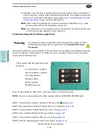


About a Typical Pneumatic Circuit
KVAL 990-F4 Service Manual
4-16
Typical Pneumatic Assembly
Pneumatic assembly setups vary in
KVAL
machines depending on where it is used and air require
-
ments.
This is a general overview of a pneumatic assembly
.
See the machine’s Air Print for
detailed information.
FIGURE 4- 7.
Typical Pneumatic Assembly
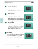
About the Coil (Solenoid)
The Solenoids are connected to the top of the manifold. Labels indicating their function and PLC
connections are attached to the solenoid body. Use this information to troubleshoot system if nec
-
essary.
FIGURE 4- 8.
Solenoids in Manifold
Air Input
Cylinder
Retract
Cylinder
Extend
Electrical Wiring Box:
Contains inputs from PLC
to Coils (Solenoids)
Manifold:
Base to accept air
input and output air.
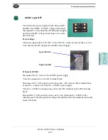
Coil (Solenoid):
Receives
input(24V) from PLC to open a port
Solenoid type will vary with machine application.
Common controls include an operational LED and
Manual operation button
Manual Activate Button:
Push to toggle solenoid to the
‘ON’ state. activates if power is off.
Indicator:
a Lit LED indicates the solenoid is in
use.Red LED= the ‘A’ Port on a single valve. If double
valve, Red LED= the ‘A’ Port and Green LED = the ‘B’
port.
Содержание 990-F4
Страница 4: ...KVAL 990 F4 Service Manual ...
Страница 28: ...How to Download the Service Application KVAL 990 F4 Service Manual 1 20 Page Intentionally Left Blank ...
Страница 30: ...Safety Sign Off Sheet KVAL 990 F4 Service Manual 1 22 ...
Страница 82: ...Collet Torque Values KVAL 990 F4 Service Manual 3 48 ...
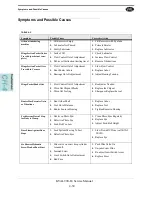
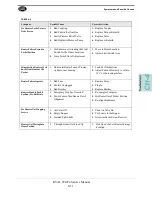
Страница 114: ...Symptoms and Possible Causes KVAL 990 F4 Service Manual 4 32 ...
Страница 117: ......