8
ESP2000D · F
ea
tur
es · Rear panel
ESP2000D · Features · Rear panel
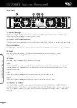
Rear Panel
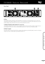
1) Input / Through
These are the input XLR connectors for channel 1 & 2 with associated 'Through Output' connectors for sending signal
to other devices. When bridge mode is used, only input 1 is active.
2) PowerCon Power Connector
The ESP2000D accepts standard PowerCon terminated AC Mains cables. The ESP2000D uses one connector per two channels.
Communication
The ESP2000D accept standard PowerCon terminated AC Mains cables. The ESP2000D uses one connector per two channels.
3) Reset
Serves as factory reset button. Resets all setup, including network settings (default settings AutoIP/DHCP).
Use a tool with maximum diameter 2mm.
4) Status
LEDs indicates amplifier and amplifier diagnostics status, these are:
AMP
Dual colour LED. When green, it indicates that the power amplifier is powered up and all monitored parameters are OK.
When red, it indicates that the amplifier is off, or some problem with the amplifier has occurred, more information can
be obtained via Ethernet.
POE
When green, it indicates that diagnostics unit is powered via Power over the Ethernet device.
DHCP
When green, it indicates that diagnostics Ethernet IP address is assigned from the DHCP server.
5) Ethernet connector
Serves as an external communication port supporting Ethernet standard, accepts RJ45, T-658B wiring. The ESP2000D
provides web-server and SNMP (Simple network management protocol). When the Ethernet cable is connected and devices
successfully establish a connection, the green LED is activated. When Ethernet communication is in progress, the orange
LED flashes.
2
3
1
4
5
Содержание ESP2000D
Страница 2: ......
Страница 20: ...ESP2000D Notes 18 ESP2000D Notes ...
Страница 21: ...ESP2000D Notes 19 ESP2000D Notes ...
Страница 22: ...ESP2000D Notes 20 ESP2000D Notes ...
Страница 23: ......


