background image

Technical module

16

Copyright © 08/2008, Küschall AG

Champion ’08

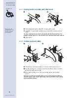
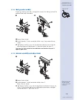
2.18  Stabilisation bar assembly

With a back height RH40.5 or larger it is possible to assemble a stabilisation bar to in-
crease the rigidity of the backrest handles.

  Remove backrest cover 

.

  Remove push handles 

 and 10cm backrest band 


 (or end band, if no push 

handles are assembled).

  Assemble a 5cm backrest band 

 or end band to the push handles 

.

  Attach the clamps 

 together with the RH socket 

 and the LH socket 

 to the 

push handles 

 below the top backrest band 

.

  Replace the push handle/backrest band/socket assembly.

 Press pin 

 and slide the stabilisation bar 

 into the RH socket 

, then swing the 

stabilisation bar upwards, press pin 

 and click the stabilisation bar into the LH 

socket 

.

2.19  Antitipper assembly and adjustment

  Remove the nut 

 from the adapter sleeve 


.

  Mount the antitipper 

 to the adapter plate 

 with the anchor sleeve 

 inserted 

into any adjacent hole.

  Tighten the nut 

 and the screw for the anchor sleeve 

.

  The height of the antitipper can be adjusted by pressing the spring pin 

, then 

sliding the inner part of the antitipper 

 to the required position until the spring pin 

locates in the correct hole.

Function control: The antitipper should measure a distance of 4–6cm from the ground 
and should swing under the chair without any difficulty.

3

1

1

2

7

4

5

6

8

9

10

2

1

2

3

4

5

6

7

Содержание Champion '08

Страница 1: ......

Страница 2: ...9 2 6 Front fork repositioning to the front frame 9 2 7 Front wheel supporter vertical adjustment 10 2 8 Front wheel replacement 10 2 9 Adapter plate adjustment to folding unit 11 2 10 Rear wheel to adapter plate adjustment 11 2 11 Parking brakes assembly and adjustment 12 2 12 Clothes guard assembly 12 2 13 Mud guard assembly 13 2 14 Armrest assembly and adjustment 13 2 15 Backrest height adjustm...

Страница 3: ...T40 to ST46 1 3 Knee to heel length UL To adjust the knee to heel length you must adjust the footrest height Chapter 2 2 The following adjustments are possible Aluminium frame UL20 UL29 high mounted footrest UL30 UL50 standard footrest Carbon frame UL30 UL39 high mounted footrest UL40 UL50 standard footrest 1 4 Rear seat to floor height SHh The following possibilities are available to adjust the re...

Страница 4: ...ic Leg length from 32 to 40 short frame Leg length from 40 to 50 long frame 45 4 3 46 5 4 3 3 47 4 3 48 5 4 3 49 5 4 3 4 3 50 5 4 5 4 3 51 5 5 4 3 53 5 4 3 54 5 4 Front seat to floor height per frame size front fork and front wheel SHv Carbon Frame 87 Leg length from 40 to 50 45 3 46 4 3 48 4 3 49 5 4 3 50 5 4 3 51 5 4 3 53 5 4 54 5 Front seat to floor height per frame size front fork and front whee...

Страница 5: ...he backrest height you must adjust or replace the backrest tubes Chap ter 2 15 Tension adjustable backrest with push handles standard RH push handle inter mediate tube Velcro straps without stabili sation bar Velcro straps with stabilisation bar 30 S S L M S 31 5 S S L M S 33 S S L S M S 34 5 S L L S M S 36 S L L S M S 37 5 S L L L S 39 S L L L S 40 5 L L L L S S L L 42 L L L S L S S L L 43 5 L L ...

Страница 6: ...M S 37 5 L L L L S 39 L L L L S 40 5 L L L L S S L L 42 L L L S L S S L L 43 5 L L L S L S M L L 45 L L L S L S M L L 46 5 L L L S L S M L L Tension adjustable backrest with push handles height adjustable RH Teles copic tube Inter mediate tube without stabilisation bar with stabilisation bar 30 S S S M S 31 5 S S S M S 33 S L L M S 34 5 S L L M S 36 S L L S M S 37 5 S L S L S 39 L L S L S 40 5 L L...

Страница 7: ...Technical module 6 Copyright 08 2008 Küschall AG Champion 08 ...

Страница 8: ...into the wheelchair frame and position the bridging sleeve accurately Re assemble the bolt set and tighten Function Control Check that the footrest is firmly attached but that it can fold easily 2 2 Footrest height adjustment Remove the 2 bolts from the frame above the footrest Extend the footrest telescope to the required length then insert the bolts into the closest holes Tighten the locking bolt...

Страница 9: ...bolts Function Control Make sure that the footplate folds easily 2 4 Footrest mounted in high position Remove the footrest from the frame Detatch the telescopic tube and footplate fixture from the footrest by removing the screw Attach the mounting bracket to the frame using the screws and nuts Attach the footrest at the desired height on the mounting brackets with the screws and the conical spacers...

Страница 10: ...upwards position A and let it tip downwards The fork is positioned correctly when it turns slightly over the lowest point and stays there position B The fork hasn t been tightened sufficiently if it turns back into the lowest position position C If tightened wrongly there is a possibility for the front wheels to start fluttering at high speeds 2 6 Front fork repositioning to the front frame The fron...

Страница 11: ...ghten both screws and 2 8 Front wheel replacement Remove the screws and the front wheel axle Remove the front wheel and attach a new front wheel or Place the front wheel in its new position 2 bushings must be slid onto the axle with a Starec wheel Skater wheel 3 Sport wheel or 5 Softroll wheel The bushings are already attached in the smooth running wheel sports wheels and pneumatic wheels Guide th...

Страница 12: ...eat angle If necessary the backrest angle can be adjusted accordingly Changing the rear seat height also changes the angle of the front wheel supporters These have to be re adjusted to 90 to the floor chapter 2 7 2 10 Rear wheel to adapter plate adjustment There are 2 different adapter plates available covering 4 possible rear wheel positions If necessary replace the adapter plate Remove the nut fr...

Страница 13: ...e is locked Tighten bolt 2 12 Clothes guard assembly Attach the seat module fixation piece to the seat module with the screws Align the clothes guard to the rear wheel and note the best hole on the clothes guard to fix it to the backrest hinge Remove backrest hinge screw then re assemble together with the clothes guard Function control Fold and unfold the backrest this must be done easily Make sure ...

Страница 14: ... mounting bracket until the mudguard is in position Tighten the screws Function control Take care that the distance between rear wheel and mud guard is equable approx 5mm 2 14 Armrest assembly and adjustment Remove the rear wheels Attach the bracket to the seat module with the screws Remount the rear wheels Slightly loosen the three screws on the height adjustment bracket then move the armrest to ...

Страница 15: ... again Reposition the backrest band correctly Tension adjustable back Remove the backrest cover Slide the backrest straps either up or down to locate the fixing bolt Remove nut and bolt Adjust the push handle or the telescopic tube to the required height then fix it with nut and bolt again Repeat on the other side than re assemble the backrest cover again Function Control Check that nothing impedes ...

Страница 16: ...andle through backrest band and fix it on the backrest with bolt Fix the upmost backrest band with screw 2 17 Backrest angle adjustment Leave the backrest in a closed position backrest lying on seat Remove the lower bolt from the side supporter Move the backrest to the required position Insert the bolt into the closest hole and tighten it again Repeat the procedure on the other side of the wheelcha...

Страница 17: ...ly Press pin and slide the stabilisation bar into the RH socket then swing the stabilisation bar upwards press pin and click the stabilisation bar into the LH socket 2 19 Antitipper assembly and adjustment Remove the nut from the adapter sleeve Mount the antitipper to the adapter plate with the anchor sleeve inserted into any adjacent hole Tighten the nut and the screw for the anchor sleeve The he...

Страница 18: ...th the spring clip Function Control The tipper aid should not touch the floor if the wheelchair is tipped backwards If the tipper aid touches the floor remove it and change the position of the spring clip This is done by removing the tube end cap then pushing the spring clip one hole further into the tube using a screwdriver 2 21 Transit wheels assembly and adjustment Attach the vertical adaptation ...

Страница 19: ...itional mounting block is needed to lower the cane holder to prevent them clashing together when the wheelchair is folded Slide the cane holder into the horizontal adaptation support and fasten it with the spring clip Remove the screw from the backrest cover then replace it together with the strap Function control The cane holder should not touch the floor when the wheelchair is tipped backwards If...

Страница 20: ...e front wheel supporters upwards 1 Backrest angle is too large Reduce backrest angle Poor or asymmetric brake grip Wrong air pressure in one or both rear wheels Correct air pressure Wrong adjustment of the brake position Adjust brake to exert correct pressure on tyre Rolling resistance is high Rear wheels are off track Adjust parallelism of rear wheels Tension on front fork axles is too high Loose...

Отзывы: