background image

- 21 -

OPTIONAL ACCESSORIES

1) Collecting rake

1.1. For machines in operation fitted with a gauge roller

kit (fixation beam + collecting rake tines.)

WMU 210

ref. 155 6342

WMU 230

ref. 155 6234

1.2. For machines in operation fitted with gauge wheels

(collecting rake tines only).

WMU 210

ref. 155 6346

WMU 230

ref. 155 6056

Note 

: The fixation beam serves as a support for the gauge wheels and the collecting rake tines.

2) Rear gauge wheels

2.2. For machines in operation and not fitted with a collecting rake (fixation beam + pair of wheels)

WMU 210

Ref. 155 6344

WMU 230

Ref. 155 6315

WMU 265

Ref. 155 6330

WMU 305

Ref. 155 6339

2.2. For machines in operation fitted with a collecting rake (pair of wheels only)

WMU 210 / WMU 230

Ref. 155 6350

WMU 265 / WMU 305

Ref. 155 6351

3) Hydraulic parallelogram offsetting

Ref. 155 6242

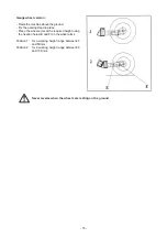
The offsetting of the machine may only be done when the machine is raised (roller or wheels are off the ground).  The

offsetting is done by a double acting hydraulic cylinder connected to the tractor’s hydraulic circuit. An lock valve

in the cylinder avoids any accidental modifications to the machines position.

Содержание WMU 210

Страница 1: ...ASSEMBLY OPERATOR S MANUAL SHREDDERS WMU 210 230 265 305 PLEASE READ CAREFULLY BEFORE USING THE MACHINE N 95603 B GB 05 96...

Страница 2: ...instruct you on the general operation of your machine He is interested that you get the best performance possible and will be glad to answer any special questions that may arise regarding the operati...

Страница 3: ...apting to the tractor 17 Machineoffsetting 18 P T O Shaft 19 Rotorspeed 20 Optional accessories 21 Collectingrake 21 Reargaugewheels 21 Hydraulicparallelogramoffsetting 21 Maintenance 22 Lubrication 2...

Страница 4: ...nufacturer The WMU 210 230 265 or 305shredders must only be operated maintained and repaired by competent persons who are familiar with machine specifications and operation and are aware of any danger...

Страница 5: ...nufacturer 13 Donotsurpassthemaximumaxleloadortheoveralltransportweightasprescribedbythetractormanufacturer 14 Do not surpass the maximum transport width authorized by road traffic regulations 15 Befo...

Страница 6: ...ot stand between the tractor and the machine when operating the outer control lever of the lift mechanism 5 Intransport themachineliftmechanismshouldbestabilizedbytractortierodstoavoidfloatationandsid...

Страница 7: ...hydraulic hoses regularly Worn or damaged hoses must be replaced immediately Replacement parts must be in accordance with manufacturer s recommendations concerning specifications and quality 6 Should...

Страница 8: ...ements immediately Use only genuine KUHN spare parts 4 When replacing cutting elements systematically inspect their securing elements as per the manufacturer s recommendations 5 Protectiondevicesarein...

Страница 9: ...N THEM GIVES THEIR PRECISE MEANING KEEP THE PICTORIALS LEGIBLE IF THEY ARE NOT REPLACE THEM To protect the user of the machine and also any other person the rear cover of the machine is fitted with a...

Страница 10: ...mplete stop before getting in contact with safety devices Rotating tools Objects and debris can be thrown a long distance Keep a safe distance from the machine Before adjusting maintaining or repairin...

Страница 11: ...9 CB White reflectors at the front CR Red reflectors at the rear...

Страница 12: ...0 540 or 1000 MiniPTOpowerrequirement kW hp 40 54 42 57 49 67 57 78 Maxi tractor power kW hp 51 70 55 75 62 85 96 130 Overallwidth mm inch 2304 7 7 2492 8 2 2870 9 5 3244 10 6 Overalllength with close...

Страница 13: ...WMU 230 680 kg 1496 lbs WMU 265 755 kg 1661 lbs WMU 305 861 kg 1894 lbs Lifting device should be attached to the lower anchorage holes 30 mm on the machine s side plates and to the top link pin Whent...

Страница 14: ...in the holes drilled at this end of the side plates Fit the yokes P to the inside of the rear crosspiece CD Bolt the wheel supports R onto the yokes P with the self locking nuts Insert the fixation pi...

Страница 15: ...g height The hammer knives must not touch the ground The minimum working heightmustnotbelowerthan25mm Gauge roller version Slightlyraisethemachinewiththetractor3 pointlift so that the rear roller is s...

Страница 16: ...arms to ensure that the roller is as close as possible to the hammer knives Replacethelargersliderandlockitinpositionusing R clip C Adjustment of the rear cover Theopening closingoftherearcover A isa...

Страница 17: ...d in place Place the wheel arms at the required height using the fixation holes E and F on the wheel arms Position 1 for a working height range between25 and 50 mm Position 2 for a working height rang...

Страница 18: ...ine is resting on the ground Uncouple the top link on the machine side Rest the PTO transmission shaft in the support G to avoid it touching the ground and being dirtied Fix the stand P in place using...

Страница 19: ...as well as the lynch pins S in the oblong holes A mobile position in the round holes F fixed position Top link It is essential to use the pivoting con nection made up of the 2 brackets M fixed on the...

Страница 20: ...from the slider and move the machine sideways in the required position Adjust the turnbuckle to the correct position and replace the locking pin Do not forget to replace the clip Offsetting by hydraul...

Страница 21: ...If required cut the guards and tubes by the same length fig 1 2 chamfer and clean the tubes fig 3 and grease the inside of the outer tube fig 4 3 Never work the PTO shaft at too sharp an angle 30 max...

Страница 22: ...g the machine at 540 or 1000 rpm is determined according to the position of the pulleys Stop the tractor motor Take out the ignition key Wait until all moving parts have come to a complete stop Positi...

Страница 23: ...n and not fitted with a collecting rake fixation beam pair of wheels WMU 210 Ref 155 6344 WMU 230 Ref 155 6315 WMU 265 Ref 155 6330 WMU 305 Ref 155 6339 2 2 For machines in operation fitted with a col...

Страница 24: ...ceperseason Oiltype SAE 90EP ISO 220 Quantity 1 5 litre Regularly check the oil level see following page Every 50 hours grease the parallelogram pivot points I with a lithium based grease The pivot pi...

Страница 25: ...o gives a belt deflection of 10 mm 0 4 see transfer Adjust adjustment screw G by the same amount so that the central transmission shaft PR is parallel to the machinerotor Retighten screws A and B as w...

Страница 26: ...tightening the nut there should still be a sideways play of 1 to 2 mm After fitting the hammer knives couple the machine to a tractor Raise it slightly and gradually increase the PTO speed until it i...

Страница 27: ...25...

Страница 28: ...hredding quality Increase in vibrations bringing with it mechanical problems on the machine Partial or total breakage of the hammer knives with risk of projections Worn hammer knives fig A The fixatio...

Страница 29: ...27 Initial hole 16 diameter F Maximum diameter 18 allowed F Initial length 110 of knive L Minimum accepted 90 length L...

Страница 30: ...s must never contact the ground Check daily the blade wear Replace immediately any irregularly worn or damaged parts Use only genuine KUHN parts Checkdailythatallnutsandboltsarecorrectlytightened Chec...

Страница 31: ...23 due to reduction of rotor speed B Excessive belt wear Replace belts and check parallelism between the rotor axis and transmission shaft Belt heating A Incorrect belt tension Retightenbelts page23 B...

Страница 32: ...ce on methods of testing Annex to AIC 1896 117 REV February 1988 Health and Safety Executive The method employed corresponds to the method No 4 in this document Unspecified testing conditions comply w...

Страница 33: ...it has been misused neglected or damaged by accident or let out on hire Nor can claims be accepted if parts other than those manufactured by us have been incorporated in any of our equipment Furtherm...

Страница 34: ...ions on all questions as to defect and to the exchange of any part or parts That all safety instructions in the Operator s Manual shall be followed and all safety guards regularly inspected and replac...

Страница 35: ...tive The Operator should respect all Health and Safety regulations as well as the Highway Code For your own safety use only genuine KUHN spare parts The manufacturer disclaims all responsibilities due...

Страница 36: ...abriques F 67706 SAVERNE CEDEX FRANCE T l 33 0 3 88 01 81 00 Fax 33 0 3 88 01 81 03 www kuhnsa com E mail info kuhnsa com Soci t Anonyme au Capital de 19 488 000 Euros For your safety and to get the b...

Отзывы: