background image

OPERATING THE ENGINE

14

ENGLISH

WARMING UP

To avoid personal injury:

A

Be sure to set the parking brake during warm-
up.

A

Be sure to set all shift levers to the "NEUTRAL"
positions and to place PTO clutch control
switch in "OFF" position during warm-up.

For five minutes after engine start-up, allow engine to
warm up without applying any load, this is to allow oil to
reach every engine part. If load should be applied to the
engine without this warm-up period, trouble such as
seizure, breakage or premature wear may develop.

B

Warm-Up Transmission Oil in the Low 

Temperature Range

Hydraulic oil serves as transmission fluid. In cold weather,
the oil may be cold with increased viscosity. This can
cause delayed oil circulation or abnormally low hydraulic
pressure for some time after engine start-up. This in turn
can result in trouble in the hydraulic system. To prevent
the above, observe the following instructions:
Warm up the engine at about 50% of rated rpm according
to the table below:

A

Do not operate the tractor under full load condition until
it is sufficiently warmed up.

JUMP STARTING

To avoid personal injury:

A

Battery gases can explode. Keep cigarettes,
sparks, and flames away from battery.

A

If tractor battery is frozen, do not jump start
engine.

A

Do not connect other end of negative (-) jumper
cable to negative (-) terminal of tractor battery.

When jump starting engine, follow the instructions below
to safely start the engine.
1. Bring helper vehicle with a battery of the same voltage

as disabled tractor within easy cable reach. "THE
VEHICLES MUST NOT TOUCH".

2. Engage the parking brakes of both vehicles and put

the shift levers in neutral. Shut both engines off.

3. Put on safety goggles and rubber gloves.
4. Ensure the vent caps are securely in place. (if

equipped)

5. Cover vent holes with damp rags. Do not allow the rag

to touch the battery terminals.

6. Attach the red clamp to the positive (red, (+) or pos.)

terminal of the dead battery and clamp the other end
of the same cable to the positive (red, (+) or pos.)
terminal of the helper battery.

7. Clamp the other cable to the negative (black, (-) or

neg.) terminal of the helper battery.

8. Clamp the other end to the engine block or frame of

the disabled tractor as far from the dead battery as
possible.

9. Start the helper vehicle and let its engine run for a few

moments. Start the disabled tractor.

10. Disconnect the jumper cables in the exact reverse

order of attachment. (Steps 8, 7 and 6).

11. Remove and discard the damp rags. 

Ambient temperature

Warm-up time 

requirement

Higher than -10

Approx. 5 minutes

-15 to -10

5 to 10 minutes

-20 to -15

10 to 20 minutes

Below -20

More than 20 minutes

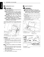
(1) Dead battery
(2) Lay a damp rag over the vent caps
(3) Jumper cables
(4) Helper battery

Содержание STV32

Страница 1: ...OTA PHILIPPINES INC 155 Panay Avenue South Trian㷅le Homes 1103 Quezon City Philippines Telephone 63 2 9201071 Taiwan SHIN TAIWAN AGRICULTURAL MACHINERY CO LTD 16 Fen㷅pin㷅 2nd Rd Taliao Shian㷅 Kaohsiun㷅 83107 Taiwan R O C Telephone 886 7 702 2333 Indonesia P T KUBOTA INDONESIA Jalan Setyabudi 279 Semaran㷅 Indonesia Telephone 62 24 7472849 Thailand SIAM KUBOTA CORPORATION CO LTD 101 19 24 Moo 20 Nav...

Страница 2: ...which the manual may be ordered the publication date the language in which the manual is written Kubota Corporation STV32 STV36 STV40 Operator s Manual TA530 8113 5 February 4 2012 the date of issue December 24 2003 English Intended use This machine is designed solely for use in customary agricultural or similar operations Use in any other way is considered as contrary to the intended use Complian...

Страница 3: ...tion Control Raised Position t Position Control Lowered Position G Draft Control Shallow Position C Draft Control Deep Position H 3 Point Lowering Speed Control M Remote Cylinder Retract L Remote Cylinder Extend 0 Hazard Warning Lights 8 Position Lamps w Headlight Low Beam 9 Headlight High Beam D Four Wheel Drive On F Four Wheel Drive Off j Fast k Slow B Creep N Steering Wheel Tilt Control 5 Audib...

Страница 4: ...s will have the most up to date information Please do not hesitate to consult with them 3SAFETY FIRST This symbol the industry s Safety Alert Symbol is used throughout this manual and on labels on the machine itself to warn of the possibility of per sonal injury Read these instructions carefully It is essential that you read the instructions and safety regulations before you attempt to assemble or...

Страница 5: ...rate the Tractor at Full Speed for the First 50 Hours 16 Changing Lubricating Oil for New Tractors 16 BOARDING AND LEAVING THE TRACTOR 16 OPERATING FOLDABLE ROPS if equipped 16 To Fold the ROPS 16 To Raise the ROPS to Upright Position 17 STARTING 18 Operator s Seat 18 Tilt Steering Adjustment 19 Head Light Switch 20 Turn Signal Hazard Light Switch 20 Position Light Switch 20 Horn Button 21 Tractor...

Страница 6: ...Rear PTO Gear Shift Lever 33 Mid PTO Gear Shift Lever 33 Stationary PTO 35 PTO Shaft Cover and Shaft Cap 35 THREE POINT HITCH DRAWBAR 36 3 POINT HITCH 37 Selecting the holes of lower links 37 Selecting the top link mounting holes 37 Drawbar 37 Lifting Rod Right 37 Top Link 37 Check Chains 38 Lower link holder 38 DRAWBAR 39 FRONT HITCH 39 HIGH HITCH 39 High Hitch 39 HYDRAULIC UNIT 40 3 POINT HITCH ...

Страница 7: ...oolant Level 56 Cleaning Grill Radiator Screen and Oil Cooler 57 Checking Brake Pedals and Clutch Pedal 57 Checking Gauges Meter and Easy Checker TM 57 Checking Head Light Hazard Light etc 57 Checking ROPS and CAB 57 Checking Movable Parts 57 EVERY 50 HOURS 58 Lubricating Grease Fittings 58 Oiling 58 Checking Engine Start System 59 Checking Wheel Bolt Torque 60 EVERY 100 HOURS 60 Changing Engine O...

Страница 8: ...RY 1 YEAR 71 Replacing Air Cleaner Primary Element and Secondary Element 71 EVERY 2 YEARS 71 Flushing Cooling System and Changing Coolant 71 Anti Freeze 72 Replacing Radiator Hose Water pipes 73 Replacing Power Steering Hose 73 Replacing HST Oil Line HST Type 73 Replacing Fuel Hose 73 SERVICE AS REQUIRED 73 Bleeding Fuel System 73 Draining Clutch Housing Water 74 Replacing Fuse 74 Replacing Light ...

Страница 9: ...OPS is loosened or removed for any reason make sure that all parts are reinstalled correctly before operating the tractor Never modify or repair a ROPS because welding bending drilling grinding or cutting may weaken the structure A damaged CAB or ROPS structure must be replaced not repaired or revised If any structural member of the CAB or ROPS is damaged replace the entire structure at your local...

Страница 10: ...overturning hazards include traveling and turning with implements and loads carried too high etc This manual sets forth some of the obvious risks but the list is not and cannot be exhaustive It is the operator s responsibility to be alert for any equipment or environmental condition that could compromise safe operation C Starting 1 Always sit in the operator s seat when starting engine or operatin...

Страница 11: ...ay on the machine or on the implement 7 Use extra caution when backing up Look behind and down to make sure area is clear before moving 8 When parking your machine if at all possible park on a firm flat and level surface if not park across a slope Set the parking brake s lower the implements to the ground remove the key from the ignition and lock the cab door if equipped and chock the wheels C Ope...

Страница 12: ...re that the tractor has come to a complete stop before dismounting 3 Avoid parking on steep slopes if at all possible park on a firm and level surface if not park across a slope with chock the wheels Failure to comply with this warning may allow the tractor to move and could cause injury or death 1 Wait until all moving components have completely stopped before getting off the tractor connecting d...

Страница 13: ...when recharging 5 Before jump starting a dead battery read and follow all of the instructions See JUMP STARTING in OPERATING THE ENGINE section 6 Keep first aid kit and fire extinguisher handy at all times 7 Disconnect the battery s ground cable before working on or near electric components 8 To avoid the possibility of battery explosion do not use or charge the refillable type battery if the flui...

Страница 14: ...oles may be invisible Do not use hands to search for suspected leaks use a piece of cardboard or wood Use of safety goggles or other eye protection is also highly recommended If injured by escaping fluid see a medical doctor at once This fluid will produce gangrene or severe allergic reaction 16 Waste products such as used oil fuel hydraulic fluid and batteries can harm the environment people pets...

Страница 15: ... 7 SAFE OPERATION ENGLISH 7 DANGER WARNING AND CAUTION LABELS ...

Страница 16: ...SAFE OPERATION 8 ENGLISH ...

Страница 17: ... 9 SAFE OPERATION ENGLISH 1 Part No TD020 3012 2 2 Part No TA040 4959 3 1AGAPAAAP0810 1AGARABAP098A 3 Part No TA040 4935 1 1AGARABAP099A ...

Страница 18: ...danger warning and caution labels with new labels from your local KUBOTA Dealer 4 If a component with danger warning and caution label s affixed is replaced with new part make sure new label s is are attached in the same location s as the replaced component 5 Mount new danger warning and caution labels by applying on a clean dry surface and pressing any bubbles to outside edge 8 CARE OF DANGER WAR...

Страница 19: ...the serial numbers now and record them in the space provided C Warranty This tractor is warranted under the KUBOTA Limited Express Warranty a copy of which may be obtained from your selling dealer No warranty shall however apply if the tractor has not been handled according to the instruction given in the Operator s Manual even it is within the warranty period C Scrapping the tractor and its proce...

Страница 20: ...2 SPECIFICATIONS ENGLISH SPECIFICATIONS SPECIFICATION TABLE ...

Страница 21: ...he right to change the specifications without notice NOTE 1 Manufacturer s estimate 2 According to EN15695 1 2009 3 Measured according to Directive 2009 76 EC 4 Measured according to Directive 2009 63 EC 5 Measured according to Directive 78 764 EEC ...

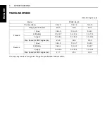
Страница 22: ...22 13 6 16 12 4 16 Range gear shift lever km h km h km h Forward 1 Low 0 to 6 6 0 to 6 5 0 to 6 1 2 Middle 0 to 12 7 0 to 12 6 0 to 11 9 3 High 0 to 28 4 0 to 28 2 0 to 26 6 Max Speed at 2850 engine rpm 29 9 29 8 28 0 Reverse 1 Low 0 to 4 8 0 to 4 7 0 to 4 4 2 Middle 0 to 9 2 0 to 9 2 0 to 8 7 3 High 0 to 20 6 0 to 20 4 0 to 19 2 Max Speed at 2850 engine rpm 21 7 21 6 20 3 ...

Страница 23: ...therwise unfit for use with the KUBOTA Tractor may result in malfunctions or failures of the tractor damage to other property and injury to the operator or others Any malfunctions or failures of the tractor resulting from use with improper implements are not covered by the warranty B Front Loader Fixation points on the body of the tractor where the front loader must be installed Install the front ...

Страница 24: ...outlined in the operator s manual of the mounted or trailed machinery or trailer and do not operate the combination tractor machine or tractor trailer unless all instructions have been followed A Forestry Application Following hazards exist a toppling trees primarily in case a rear mounted tree grab crane is mounted at the rear of the tractor b penetrating objects in the operator s enclosure prima...

Страница 25: ... Controls ILLUSTRATED CONTENTS 1 Hourmeter Tachometer 28 2 Turn signal Hazard light indicator 20 3 Easy Checker TM 10 27 4 Turn signal light switch 20 5 Head light switch 20 6 Horn button 21 7 Position light switch 20 8 Coolant temperature gauge 28 9 Fuel gauge 28 10 Key switch 10 11 Hazard light switch 20 ...

Страница 26: ...control switch 32 4 Cruise control lever 26 15 Remote control valve lever if equipped 41 5 Operator s seat 18 16 Remote control valve if equipped 42 6 Bi Speed turn switch 24 17 3 Point hitch lowering speed knob 40 7 Tool box ROPS type 54 18 Parking brake lever 10 25 29 8 Trailer electrical outlet 31 19 Front wheel drive lever 24 9 Hand throttle lever 25 20 Differential lock pedal 29 10 Brake peda...

Страница 27: ... ON and implement lowered to the ground Check item Walk around inspection Check engine oil level Check transmission oil level Check coolant level Check air cleaner evacuator valve When used in a dusty place Clean grill radiator screen and oil cooler Check brake and clutch pedal Check indicators gauges and meter Check lights Check ROPS Check movable parts Refuel See DAILY CHECK in PERIODIC SERVICE ...

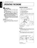
Страница 28: ...gine A Do not use starting fluid or ether A To protect the battery and the starter make sure that the starter is not continuously turned for more than 10 seconds STARTING THE ENGINE 1 To set the parking brake 1 Interlock the brake pedals 2 Depress the brake pedals 3 Pull the lever to park 2 To release the parking brake depress the brake pedals push release button and push down parking brake lever ...

Страница 29: ...o the pedal automatically returns to the neutral position 2 Make sure the fuel cock is in the open position 1 Fuel cock A CLOSE B OPEN 3 Make sure the cruise control lever is in NEUTRAL position Place the Speed control Pedal in NEUTRAL position Place the range gear shift lever in NEUTRAL position 1 Cruise control lever 2 Speed control pedal 3 Range gear shift lever N NEUTRAL POSITION NEUTRAL POSIT...

Страница 30: ...in OFF position ON OFF A PUSH 5 Place the hydraulic control lever in LOWEST position 1 Position control lever A DOWN 6 Set the throttle lever to about 1 2 way 1 Hand throttle lever INCREASE DECREASE 7 Insert the key into the key switch and turn it ON OFF ON PREHEAT START ...

Страница 31: ...elow 5 C and the engine is very cold If the engine fails to start after 10 seconds turn off the key for 30 seconds Then repeat steps 9 and 10 To protect the battery and the starter make sure that the starter is not continuously turned for more than 10 seconds If a lamp is still on immediately stop the engine and determine the cause STOPPING THE ENGINE A If key does not stop the engine consult your...

Страница 32: ...ine A Do not connect other end of negative jumper cable to negative terminal of tractor battery When jump starting engine follow the instructions below to safely start the engine 1 Bring helper vehicle with a battery of the same voltage as disabled tractor within easy cable reach THE VEHICLES MUST NOT TOUCH 2 Engage the parking brakes of both vehicles and put the shift levers in neutral Shut both ...

Страница 33: ...round starting system A Use only same voltage for jump starting A Use of a higher voltage source on tractor s electrical system could result in severe damage to tractor s electrical system Use only matching voltage source when Jump starting a low or dead battery condition ...

Страница 34: ...ecially observed in the case of new tractors BChanging Lubricating Oil for New Tractors The lubricating oil is especially important in the case of a new tractor The various parts are not broken in and are not accustomed to each other small metal grit may develop during the operation of the tractor and this may wear out or damage the parts Therefore care should be taken to change the lubricating oi...

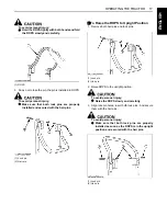
Страница 35: ...hair pins BTo Raise the ROPS to Upright Position 1 Remove both hair pins and lock pins 2 Raise ROPS to the upright position To avoid personal injury A Raise the ROPS slowly and carefully 3 Align lock pin holes insert both lock pins And secure them with the hair pins To avoid personal injury A Make sure that both lock pins are properly installed as soon as the ROPS is in the upright position and se...

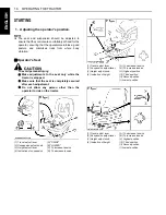
Страница 36: ...ther than the operator to ride on the tractor 1 Adjusting the operator s position 1 Travel adjust lever 2 Suspension adjust knob 3 Height adjust lever 4 Indication of suspension A RAISE B LOWER C To increase tension D To decrease tension 1 Travel adjust lever 2 Suspension adjust lever 3 Height adjust knob 4 Indication of height A To decrease tension B To increase tension O Highest position III Thi...

Страница 37: ... until the minus sign is facing forward as shown and cranking the ratchet handle The ratchet action is now reversed C Height adjustment A D type Pull and slide the height adjust lever to desired position while sitting in the seat B C type Turn the height adjust knob to desired position while sitting in the seat A After adjusting the operator s seat be sure to check to see that the seat is properly...

Страница 38: ...ushed the hazard lights flash along with the indicator on the instrument panel Press the hazard light switch again to turn off the light The hazard light switch is operative even when the key switch is at OFF position BPosition Light Switch To activate the position lights Press the position light switch the following lights are activated When this switch is pressed again those lights are off C Pos...

Страница 39: ...und when the key switch is in the ON position and the horn button pressed BTractor Lights 1 Head light 2 Front turn signal Hazard light 3 Front position light 4 Tail light 5 Rear turn signal Hazard light 6 Brake stop light 7 Number plate light 1 Horn button A PUSH ...

Страница 40: ...ng on icy wet or loose surfaces make sure the tractor is correctly ballasted operated at reduced speed operated with front wheel drive engaged if equipped A The braking characteristics are different between two and four wheel drive Be aware of the difference and use carefully 1 Before operating the tractor on the road or before applying the parking brake be sure to interlock the right and left ped...

Страница 41: ...e tractor is completely stopped and the speed control pedal is neutral position IMPORTANT To avoid transmission and shift linkage damage when shifting A Completely stop the tractor using the brake pedals A Do not force the range gear shift lever A If it is difficult to shift the lever into 1 2 or 3 from neutral position On slopes be sure to set the parking brake before starting the procedure 1 Sli...

Страница 42: ...g wheel and move the lever A Tires will wear quickly if front wheel drive is engaged on paved roads C Front wheel drive is effective for the following jobs 1 When greater pulling force is needed such as working in a wet field when pulling a trailer or when working with a front end loader 2 When working in sandy soil 3 When working on a hard soil where a rotary tiller might push the tractor forward...

Страница 43: ...tight spaces A When the Bi speed turn switch is set to ON and overload is applied to the front wheels the front wheels may stop when the turning angle of the front wheels is 34 degrees or more This is not a problem but the Bi speed clutch is slipping Set the Bi speed turn to OFF when the front wheels stop making it difficult to continue operation A Do not use the Bi speed turn when operating the f...

Страница 44: ...ntrol won t be released with single brake activation Cruise control is designed for tractor operating efficiency and operator comfort This device will provide a constant forward operating speed by mechanically holding the cruise control lever at the selected position C To engage Cruise Control Device 1 The proper forward speed will be maintained if you apply the cruise control lever at any positio...

Страница 45: ...e engine suddenly slows down or accelerates A Unusual noises suddenly are heard A Exhaust fumes suddenly become very dark While driving make the following checks to see that all the parts are functioning normally BEasy Checker TM A For checking and servicing of your tractor consult your local KUBOTA Dealer for instructions 1 Cruise control lever A INCREASE B DECREASE C NEUTRAL 1 Easy checker TM 2 ...

Страница 46: ...removing cap completely 1 With the key switch at ON this gauge indicates the temperature of the coolant C for cold and H for hot 2 If the indicator reaches the H position red zone engine coolant is overheated Check the tractor by referring to TROUBLESHOOTING section BHourmeter Tachometer This meter gives readings for engine speed PTO shaft speed and the hours the tractor has been operated 1 The ta...

Страница 47: ...dental rolling of the machine OPERATING TECHNIQUES BDifferential Lock To avoid personal injury due to loss of steering control A Do not operate the tractor at high speed with differential lock engaged A Do not attempt to turn with the differential lock engaged A Be sure to release the differential lock before making a turn in field conditions If one of the rear wheels should slip step on the diffe...

Страница 48: ...ELS AND BALLAST section 2 Slow down for slopes rough ground or sharp turns especially when transporting heavy rear mounted equipment 3 Before descending a slope shift to a gear low enough to control speed without using brakes BTransport the Tractor Safely 1 The tractor if damaged must be carried on a truck Secure the tractor tightly with ropes 2 Follow the instruction below when towing the tractor...

Страница 49: ...d decreases in time with the movement of the HST pedal HST pedal can be operated with the feeling of an accelerator pedal A Do the following to have the accelerator interlocked or not 1 Trailer electrical outlet Terminal Function Color of wire harness 1 Turn signal LH Green White 2 3 Ground Black 4 Turn signal RH Red White 5 Tail RH Yellow Red 6 Brake Stop Yellow 7 Tail LH Yellow White 1 Accessory...

Страница 50: ...ockwise to the position and release your hand In the ON position switch slightly rises itself To Turn OFF Tap on top of the switch and the switch will return to the OFF position In the OFF position the switch stays low profile A To avoid shock loads to the PTO reduce engine speed when engaging the PTO then open the throttle to the recommended speed A There are PTO 540 and 540E rpm indicated marks ...

Страница 51: ...perated at low speed Use only when this higher rpm is specifically recommended by the implement manufacturer The rear PTO gear shift lever can be set to either 540 rpm or 800 rpm position Move this lever to either position with the PTO clutch control switch set to OFF A When the PTO 800 rpm mode is not used loosen the knob bolt shift the control fixture in the direction of arrow and fix it in this...

Страница 52: ...d PTO The mid PTO is available for KUBOTA approved implements Mid PTO lever Rear PTO lever PTO clutch Rear PTO speed Mid PTO speed OFF 540 OFF ON 540 2670 0 NEUTRAL 0 800 800 2717 ON 540 OFF ON 540 2670 2500 2734 NEUTRAL 0 800 800 2717 1 Mid PTO ...

Страница 53: ...on A If the rear PTO system is engaged and the parking brake is released the engine stops automatically BPTO Shaft Cover and Shaft Cap Keep the PTO shaft cover in place at all times Replace the PTO shaft cap when the shaft is not in use Before connecting or disconnecting a drive shaft to PTO shaft be sure engine is OFF When connecting or disconnecting the joint to PTO shaft raise up the PTO shaft ...

Страница 54: ...OINT HITCH DRAWBAR ENGLISH THREE POINT HITCH DRAWBAR 1 Top link 2 Lifting rod Left 3 Check chains 4 Turn buckle 5 Lower link 6 Lifting rod Right 7 Lower link holder 8 Drawbar if equipped 9 High hitch if equipped ...

Страница 55: ...mplement unless parking brake is applied A Before attaching or detaching implement locate the tractor and implement on a firm level surface A Whenever an implement or other attachment is connected to the tractor 3 point hitch check full range of operation for interference binding or PTO separation BLifting Rod Right Level a 3 point mounted implement from side to side by turning the adjusting handl...

Страница 56: ... to control horizontal sway of the implement After adjustment re set the snap pin BLower link holder When operating the tractor without a 3 point hitch implement it is necessary to lock the lower links to prevent them from hitting the tractor rear wheels 1 Turnbuckle 2 Snap pin 1 Lower link holder ...

Страница 57: ...ry A Never pull from the top link the rear axle or any point above the hitch Doing so could cause the tractor to tip over rearward causing personal injury or death BHigh Hitch A The drawbar was tested and approved in accordance with the EEC Directive 89 173 Annex 4 dynamic method Drawbar High hitch 1 PTO shaft 2 Drawbar 3 Drawbar pin 1 Front hitch 1 High hitch EEC Approved No D e1 0029 Value of D ...

Страница 58: ...h Do not stand on or near the implement or between the implement and tractor when operating the 3 point hitch controls BPosition Control This will control the working depth of 3 point implements regardless of the amount of pull required BFloat Control Place the position control lever in the float position to make the lower links move freely along with the ground conditions B3 point Hitch Lowering ...

Страница 59: ...d side of transmission case REMOTE HYDRAULIC CONTROL SYSTEM if equipped BRemote Control Valve Lever Move the lever to the FORWARD or REARWARD position and hold This will raise or lower the implement Lever will return to neutral when released A Do not hold the lever in the REARWARD or FORWARD position once the remote cylinder has reached the end of the stroke as this will cause oil to flow through ...

Страница 60: ...ng valve 2 Turn the auxiliary control valve selector lever counter clockwise all the way to utilize as double acting valve 1 Remote control valve lever a 2 Remote control valve lever b 3 Remote control valve lever c A FORWARD B REARWARD Pressure Returning Double acting Single acting Lever a Forward Rearward Forward Rearward Port A Out In Out In B In Out Lever b Forward Rearward Port C Out In D In ...

Страница 61: ...k chains Remarks Moldboard plow Light soil Medium soil Heavy soil 1 or 2 2 or 3 3 Position control YES NO Loose Adjust the check chains so that the implement can move 5 to 6 cm laterally Check chains should be tight enough to prevent excessive implement movement when implement is in raised position Disc plow 2 or 3 Harrower spike springtooth disc type 2 or 3 Sub soiler Weeder ridger 3 YES Tighten ...

Страница 62: ...ith a full load of front weights BDual Tires Dual tires are not approved WHEEL ADJUSTMENT To avoid personal injury A When working on slopes or when working with trailer set the wheel tread as wide as practical for maximum stability A Support tractor securely on stands before removing a wheel A Do not work under any hydraulically supported devices They can settle suddenly leak down or be accidental...

Страница 63: ...s need to use Front tire spacer kit To avoid personal injury A Before jacking up the tractor park it on a firm and level ground and chock the rear wheels A Fix the front axle to keep it from swinging A Select jacks that withstand the machine weight and set them up as shown below Models STV32 STV36 STV40 Tires 6 00 12 Farm 24 x 8 50 14 Turf 23 x 8 50 14 Industry Tread 1030 1030 1040 1 Jack points ...

Страница 64: ...ft tires A Always attach tires as shown in the drawings A If not attached as illustrated transmission parts may be damaged A When re fitting or adjusting a wheel tighten the bolts to the following torques then recheck after driving the tractor 200m 200yards and thereafter according to service interval See MAINTENANCE section Rear 9 5 22 Farm 13 6 16 Turf 12 4 16 Industry 1 215 N m 22 kgf m ...

Страница 65: ...llast is used A Do not fill the front wheels with liquid to maintain steering control BFront Ballast Add weights if needed for stability and improve traction Heavy pulling and heavy rear mounted implements tend to lift front wheels Add enough ballast to maintain steering control and prevent tip over Remove weight when no longer needed C Front End Weights option The front end weights can be attache...

Страница 66: ... Use of this method of weighting the wheels has the full approval of the tire companies See your tire dealer for this service Liquid weight per tire 75 Percent filled A Do not fill tires with water or solution more than 75 of full capacity to the valve stem level at 12 o clock position BRear Counter Weight To operate the machine with a front loader or other front implement attached it is necessary...

Страница 67: ...ry condition Check every 100 Hr 65 5 9 Air cleaner element Single type Clean every 100 Hr 61 1 Replace every 1 Year 71 10 Air cleaner element Double type Primary element Clean every 100 Hr 62 1 Replace every 1 year 71 2 Secondary element Replace every 1 year 71 11 Fuel filter element Clean every 100 Hr 62 Replace every 400 Hr 70 12 Parking brake Adjust every 100 Hr 66 13 Fuel line Check every 100 ...

Страница 68: ...ry 200 Hr 68 Replace every 2 years 73 19 Power steering oil line Check every 200 Hr 69 Replace every 2 years 73 20 HST oil line HST Check every 200 Hr 69 Replace every 2 years 73 21 Transmission fluid Change every 400 Hr 70 22 Front axle case oil Change every 400 Hr 70 23 Front axle pivot Adjust every 600 Hr 71 24 Engine valve clearance Adjust every 800 Hr 71 4 25 Cooling system Flush every 2 year...

Страница 69: ...hen a low sulfur or high sulfur fuel is employed No Locations Capacities Lubricants STV32 STV36 STV40 1 Fuel 29 5 L No 2 D diesel fuel No 1 D diesel fuel if temperature is below 10 2 Coolant 6 1 L Fresh clean soft water with anti freeze 3 Engine crankcase with filter 6 7 L Engine oil API Service Classification CD CE or CF Above 25 SAE30 SAE10W 30 or 15W 40 0 to 25 SAE20 SAE10W 30 or 15W 40 Below 0...

Страница 70: ...em and complete lubrication of the transmission it is important that a multi grade transmission fluid be used in this system We recommend the use of KUBOTA SUPER UDT fluid for optimum protection and performance Consult your local KUBOTA Dealer for further detail Do not mix different brands or grades A Indicated capacity of water and oil are manufacturer s estimate ...

Страница 71: ...g A Do not touch muffler or exhaust pipes while they are hot Severe burns could result A Support hood with other hand while unlocking support link BHood To open the hood twist the mascot to release the latch and open the hood A To close the hood hold the hood and release the support link BEngine Side Cover and Front Grill 1 To remove the front grill loosen knob bolts pull outward as indicated by a...

Страница 72: ...he ground A All residual pressure of the hydraulic system released A Stop the engine and remove the key BWalk Around Inspection Look around and under the tractor for such items as loose bolts trash build up oil or coolant leaks broken or worn parts BChecking and Refueling To avoid personal injury A Do not smoke while refueling A Be sure to stop the engine before refueling 1 Turn the key switch to ...

Страница 73: ...k engine oil before starting the engine or 5 minutes or more after the engine has stopped 3 To check the oil level draw out the dipstick wipe it clean replace it and draw it out again Check to see that the oil level lies between the two notches If the level is too low add new oil to the prescribed level at the oil inlet See LUBRICANTS in MAINTENANCE section A When using an oil of different maker o...

Страница 74: ...st stop and allow sufficient time for excess pressure to escape before removing the cap completely 1 Check to see that the coolant level is between the FULL and LOW marks of recovery tank 2 When the coolant level drops due to evaporation add soft water only up to the full level In case of leakage add anti freeze and soft water in the specified mixing ratio up to the full level See Flushing Cooling...

Страница 75: ...or free travel and smooth operation 2 Adjust if incorrect measurement is found See Adjusting Clutch Pedal and Adjusting Brake Pedal in EVERY 100 HOURS in PERIODIC SERVICE section BChecking Gauges Meter and Easy Checker TM 1 Inspect the instrument panel for broken gauge s meter s and Easy Checker TM lamps 2 Replace if broken BChecking Head Light Hazard Light etc 1 Inspect the lights for broken bulb...

Страница 76: ...wet and muddy conditions lubricate grease fittings more often BOiling To avoid personal injury A Be sure to stop the engine and remove the key before oiling 1 Grease fitting Top link 2 Grease fitting Lifting rod RH 1 Battery terminals 1 Grease fitting Brake pedal shaft 1 Grease fitting Clutch pedal shaft 1 Grease fitting Cruise control lever 1 Hand throttle cable 2 Accelerator cooperative cable ...

Страница 77: ...gage the mid PTO gear shift lever 3 Depress the clutch pedal fully 4 Place the speed control pedal in NEUTRAL position 5 Turn the key to START position 6 The engine must not crank 7 If it cranks consult your local KUBOTA Dealer for this service C Test Switch for the clutch pedal 1 Sit on the operator s seat 2 Disengage the PTO clutch control switch and disengage the rear and mid PTO gear shift lev...

Страница 78: ...d personal injury A Be sure to stop the engine before changing the oil A Allow engine to cool down sufficiently oil can be hot and can burn 1 To drain the used oil remove the drain plug at the bottom of the engine and drain the oil completely into the oil pan All the used oil can be drained out easily when the engine is still warm 2 After draining reinstall the drain plug 3 Fill with the new oil u...

Страница 79: ...ght and check if it is damaged or not referring to the instructions on the label attached to the case 3 Replace air cleaner element Once yearly or after every sixth cleaning whichever comes first A Check to see if the evacuator valve is blocked with dust A The air cleaner uses a dry element never apply oil A Do not run the engine with filter element removed A Be sure to refit the cover with the ar...

Страница 80: ...improperly fitted evacuator valve will not function and dust will adhere to the element A Do not touch the secondary element except in cases where replacing is required See Replacing Air Cleaner Secondary Element in Every 1 Year maintenance C Evacuator Valve Open the evacuator valve once a week under ordinary conditions or daily when used in a dusty place to get rid of large particles of dust and ...

Страница 81: ...eflection of the belt falls within acceptable limits 4 Replace fan belt if it is damaged BChecking Fuel Line 1 Check to see that all lines and hose clamps are tight and not damaged 2 If hoses and clamps are found worn or damaged replace or repair them at once A If the fuel line is removed be sure to properly bleed the fuel system See Bleeding Fuel System in SERVICE AS REQUIRED in PERIODIC SERVICE ...

Страница 82: ... chock the wheels before checking brake pedal 1 Release the parking brake 2 Slightly depress the brake pedals and measure free travel at top of pedal stroke 3 If adjustment is needed loosen the lock nut and turn the brake rod to adjust the rod length within acceptable limits 4 Retighten the lock nut Proper clutch pedal free travel 20 to 30 mm on the pedal 1 Lock nut 2 Turn buckle A Free travel Pro...

Страница 83: ...void personal injury A When the battery is being activated hydrogen and oxygen gases in the battery are extremely explosive Keep open sparks and flames away from the battery at all times especially when charging the battery A When charging the battery ensure the vent caps are securely in place if equipped A When disconnecting the cable from the battery start with the negative terminal first When c...

Страница 84: ...king Brake Lever To avoid personal injury A Stop the engine and chock the wheels before checking parking brake 1 Raise the parking brake lever to the parking position while counting the ratchet sound made by the parking brake lever 2 If adjustment is needed loosen the lock nut and adjust the parking brake rod length with in acceptable limit 3 Retighten the lock nut Tractor model Battery TYPE Volts...

Страница 85: ...ak through the seal and be sure to check the oil level on the dipstick Then replenish the engine oil up to the prescribed level A To prevent serious damage to the engine use only a KUBOTA genuine filter BReplacing Hydraulic Oil Filter Replacing Transmission Oil Filter HST Type To avoid personal injury A Be sure to stop the engine before changing the oil filter cartridge A Allow engine to cool down...

Страница 86: ...hours of operation or six months whichever comes first 1 If hose clamps are loose or water leaks tighten bands securely 2 Replace hoses and tighten hose clamps securely if radiator hoses are swollen hardened or cracked Replace hoses and hose clamps every 2 years or earlier if checked and found that hoses are swollen hardened or cracked C Precaution at Overheating Take the following actions in the ...

Страница 87: ... Measure distance between tire beads at front of tire hub height 5 Measure distance between tire beads at rear of tire hub height 6 Front distance should be 2 to 8 mm less than rear distance If not adjust tie rod length C Adjusting procedures 1 Detach the snap ring 2 Loosen the tie rod nut 3 Turn the tie rod joint to adjust the rod length until the proper toe in measurement is obtained 4 Retighten...

Страница 88: ...iately after changing the transmission fluid Run the engine at medium speed for a few minutes to prevent damage to the transmission BReplacing Fuel Filter Element See Cleaning Fuel Filter in EVERY 100 HOURS in PERIODIC SERVICE section BChanging Front Axle Case Oil 1 To drain the used oil remove the right and left drain plugs and filling plug at the front axle case and drain the oil completely into...

Страница 89: ...iator cap while coolant is hot When cool slowly rotate cap to the first stop and allow sufficient time for excess pressure to escape before removing the cap completely 1 Stop the engine and let cool down 2 To drain the coolant open the radiator drain plug and remove radiator cap The radiator cap must be removed to completely drain the coolant 3 After all coolant is drained close the drain plug 4 F...

Страница 90: ...act with the skin or clothing wash it off immediately A Do not mix different types of Antifreeze The mixture can produce chemical reaction causing harmful substances A Antifreeze is extremely flammable and explosive under certain conditions Keep fire and children away from antifreeze A When draining fluids from the engine place some container underneath the engine body A Do not pour waste onto the...

Страница 91: ...s See Checking Radiator Hose and Clamp in EVERY 200 HOURS in PERIODIC SERVICE section BReplacing Power Steering Hose Replace the hoses and clamps See Checking Power Steering Line in EVERY 200 HOURS in PERIODIC SERVICE section BReplacing HST Oil Line HST Type Replace the hoses and clamps See Checking HST Oil Line in every 200 hours maintenance BReplacing Fuel Hose Replace the hoses and clamps See C...

Страница 92: ...otected from potential damage by fuses A blown fuse indicates that there is an overload or short somewhere in the electrical system If any of the fuses should blow replace with a new one of the same capacity A Before replacing a blown fuse determine why the fuse blew and make any necessary repairs Failure to follow this procedure may result in serious damage to the tractor electrical system Refer ...

Страница 93: ... A Protected circuit 1 30 Starter 2 15 Hazard 3 10 Position 4 10 Alternator panel 5 15 Head light Horn 6 10 Control box PTO solenoid 7 5 Key stop 8 10 Work light 9 10 Brake 10 10 Flasher 11 Slow blow fuse 50 main 40 Key switch 40 Key stop 40 Glow Light Capacity Head light 45W 40W Tail light 10W Brake stop light 21W Turn signal Hazard light 21W Front position light 10W Instrument panel light 1 7W W...

Страница 94: ...al moving parts for about five minutes 6 Keep the clutch disengaged If the clutch is left engaged for a long period of time the clutch plate may rust making clutch disengagement impossible at the next operation 7 With all implements lowered to the ground coat any exposed hydraulic cylinder piston rods with grease 8 Remove the battery from the tractor Store the battery following the battery storage...

Страница 95: ...ine oil transmission hydraulic oil engine coolant and any attached implements 6 Start the engine Observe all gauges If all gauges are functioning properly and reading normal move the tractor outside Once outside park the tractor and let the engine idle for at least five minutes Shut the engine off and walk around tractor and make a visual inspection looking for evidence of oil or water leaks 7 Wit...

Страница 96: ...from the engine charge and store it indoors Install it on the tractor only when the tractor is going to be used Insufficient engine power A Insufficient or dirty fuel A The air cleaner is clogged A Check the fuel system A Clean or replace the element Engine stops suddenly A Insufficient fuel A Refuel A Bleed the fuel system if necessary Exhaust fumes are colored Black A Fuel quality is poor A Too ...

Страница 97: ...h visibility for night work A Front end weights For front ballast A Mounting Kit Front end weights To mount Front end weights A Rear Wheel Weights For rear ballast A Secondary element For double air cleaner A Exhaust Extension Adaptor To change the exhaust direction A Accelerator cooperative KIT ...

Страница 98: ...es 25 55 100 Tire combination 2 unit kg Front tire Rear tire Technically permissible maximum laden mass Tractor payload Tire size 24x8 50 14 13 6 16 Maximum permissible load of the tire 425 800 Maximum axle load 850 1600 2100 870 1030 Minimum limit percentages 25 55 100 Tire combination 3 unit kg Front tire Rear tire Technically permissible maximum laden mass Tractor payload Tire size 23x8 50 14 1...

Страница 99: ...igh hitch AL KO Kober type 700 690 685 375 300 High hitch Scharmuller Type 256010 690 680 675 395 300 644 5 634 5 629 5 330 599 589 584 380 553 5 543 5 538 5 420 508 498 493 460 462 5 452 5 447 5 520 417 407 402 570 371 5 361 5 356 5 630 326 316 311 690 Drawbar unit kg Permissible towable masses Total technically permissible mass of the tractor trailer combination Unbraked towable mass 1500 3600 I...

Страница 100: ... with four wheel drive 45 Fuel Filter 62 Fuel Filter Element 70 Fuel Gauge 28 Fuel Hose 73 Fuel Line 63 Fuel System 73 Fuse 74 Gauges Meter and Easy Checker TM 57 Grill Radiator Screen and Oil Cooler 57 Hand Throttle Lever 25 Head Light Switch 20 Head Light Hazard Light etc 57 High Hitch 39 Hood 53 Horn Button 21 Hourmeter Tachometer 28 HST Oil Line HST Type 73 HST Oil Line HST Type Power Steering...

Страница 101: ...tationary PTO 35 Stopping 27 Tilt Steering Adjustment 19 To Fold the ROPS 16 To Raise the ROPS to Upright Position 17 Toe in 69 Tool Box ROPS Type 54 Top Link 37 Tractor Lights 21 Trailer Electrical Outlet 31 Trailer Load Capacity 81 Transmission Fluid 70 Transmission Fluid Level 56 Transport the Tractor Safely 30 Turn Signal Hazard Light Switch 20 Walk Around Inspection 54 Warm Up Transmission Oi...

Страница 102: ......

Отзывы: