


GENERATOR
GL6000A-AU-B, GL6000D-AU-B,GL9000A-AU-B, GL9000D-AU-B, WSM
2-M5
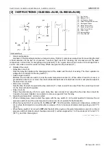
[2] INSTRUCTIONS (GL6000A-AU-B, GL9000A-AU-B)
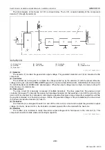
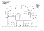
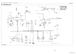
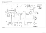
1. Circuit configuration
As shown in the block diagram above, emergency relay (5) (EG-1) comprises a delay timer for preventing the start
of fault detection till the rise of oil pressure: a sensor input circuit for checking the oil pressure and the water
temperature: a drive timer for energizing a stop solenoid (11) for a given time period in case of a fault input from a
sensor: and a drive circuit for a external relay: Which energize the stop solenoid (11).
2. Details of the circuit
• Delay timer circuit (6)
Sets the delay time between the disengagement of the starter and the start of sensing. The timer operates on
voltage from terminal 50 of the key switch (1).
• Sensor input circuit (7)
Monitors the oil pressure switch (3) and the water temperature sensor (4). When either of switch or sensor is
grounded for about 4 ms or more, the circuit will decide that sensor trouble has occurred, and provide output to
the drive timer circuit (8).
• Drive timer circuit (8)
Sets the time for which to operate the stop solenoid (11). Upon receipt of an output from the sensor input circuit
(7), the timer will start to operate.
• Drive circuit (9)
Drives the external relay (10) for a given delay time upon receipt of an output from the drive timer circuit (8).
Consists of a power transistor, and a diode to remove surge volts from the relay.
3. Operating principle EG-1 controls so that:
• While an attempt was made to start the engine with the key switch (1) in the start position 50 terminal, the oil
pressure switch (3) and the water temperature sensor (4) do not operate for fault detection.
• When the key switch (1) is returned to the
ON
and
"AC"
, from the position mentioned in step above, a state will
occur where fault detection is possible after an elapse of 6 to 12 seconds (at starter starting voltage and 20 °C
(68 °F)).
• When the key switch (1) is turned to
OFF
after the start of the engine, or the water temperature sensor (4) or the oil
pressure switch (3) detects a fault, the stop solenoid (11) will be energized for 7 to 13 seconds (at 12 V and 20 °C
(68 °F)), and then disenergized.
9Y1211607GRM0006US0
(1) Key Switch
(2) Battery (12 V)
(3) Oil Pressure Switch
(4) Water Temperature Sensor
(5) Emergency Relay
(6) Delay Timer Circuit
(7) Sensor Input Circuit
(8) Drive Timer Circuit
(9) Drive Circuit
(10) External Relay
(11) Stop Solenoid
KiSC issued 06, 2016 A
Содержание GL6000A-AU-B
Страница 3: ...I INFORMATION KiSC issued 06 2016 A ...
Страница 20: ...G GENERAL KiSC issued 06 2016 A ...
Страница 56: ...1 ENGINE KiSC issued 06 2016 A ...
Страница 124: ...2 GENERATOR KiSC issued 06 2016 A ...
Страница 142: ...GENERATOR GL6000A AU B GL6000D AU B GL9000A AU B GL9000D AU B WSM 2 M17 2 GL6000D AU B KiSC issued 06 2016 A ...
Страница 143: ...GENERATOR GL6000A AU B GL6000D AU B GL9000A AU B GL9000D AU B WSM 2 M18 3 GL9000A AU B KiSC issued 06 2016 A ...
Страница 144: ...GENERATOR GL6000A AU B GL6000D AU B GL9000A AU B GL9000D AU B WSM 2 M19 4 GL9000D AU B KiSC issued 06 2016 A ...


