KTR Kupplungstechnik
GmbH
D-48407 Rheine
POLY
Operating-/Assembly Instructions
KTR-N
sheet:
edition:
49610 EN
14 of 24
9
Gezeichnet: 11.03.10
Pz/Bru
Ersatz für:
KTR-N vom 25.04.07
Schutzvermerk
ISO 16016 beachten. Geprüft:
16.03.10 Pz
Ersetzt durch:
4 Assembly
4.6 Hint Regarding the Finish Bore
KTR supplies unbored or pilot bored coupling parts and spare parts on explicit customer´s request. These parts
are additionally labelled with the symbol .
!
C A U T I O N !
The orderer is responsible for all subsequently made machinings to unbored or pilot bored
and to finish machined coupling parts and spare parts. KTR does not assume any warranty
claims resulting from insufficient refinish.
P R E C A U T I O N !
Any mechanical rework to couplings that are used in hazardous areas require an explicit
release by KTR.
The orderer must send a drawing to KTR acc. to which the manufacture must be made. KTR
checks this drawing and returns it to the orderer with approval.
4.7 Displacements - Alignment of the Couplings
The
POLY
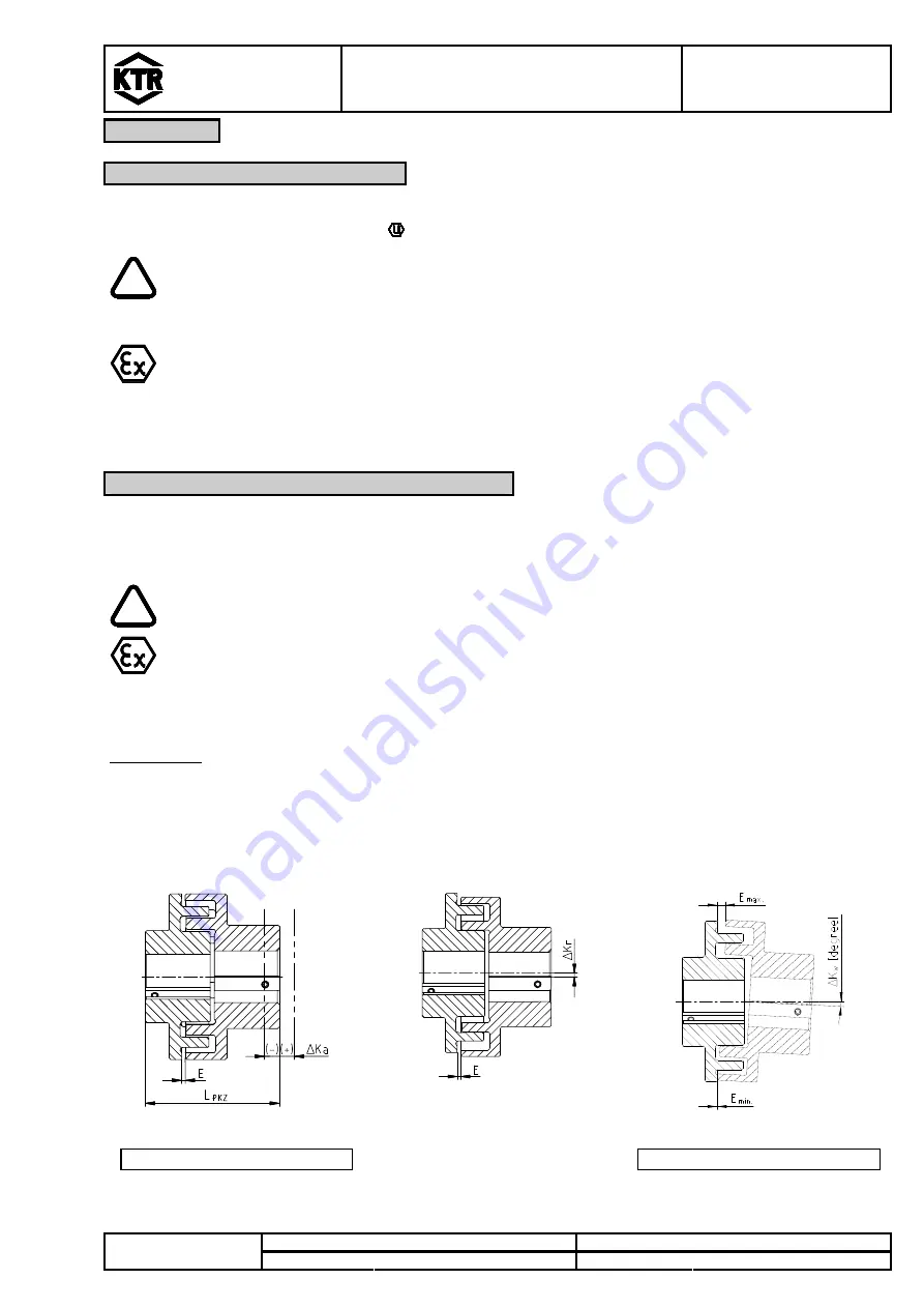
compensates for displacements produced by the shafts to be combined as shown in table 10.
Excessive misalignment may be caused by inaccurate alignment, production tolerances, thermal expansion, shaft
deflection, twisting of machine frames, etc.
!
C A U T I O N !
In order to ensure a long lifetime of the coupling and to avoid dangers regarding the use in
hazardous areas, the shaft ends must be accurately aligned.
Please absolutely observe the displacement figures indicated (see table 10). If the figures
are exceeded, the coupling is damaged.
The exacter the alignment of the coupling, the higher is its lifetime.
In case of a use in hazardous areas for the explosion group IIC (marking II 2GD c IIC T X),
only the half displacement figures (see table 10) are permissible.
Please note:
•
The displacement values mentioned in table 10 are maximum values which may not occur at the same time. If
the radial and the angular displacement occur at the same time, the sum of the displacements may not exceed
Δ
K
r
or
Δ
K
W.
•
Please check with a dial gauge, ruler or feeler whether the permissible displacement figures of table 10 can be
observed.
axial displacements
radial displacements angular
displacements
L
PKZ perm.
= L
PKZ
+
Δ
Ka [mm]
Δ
Kw = E
max.
- E
min.
[mm]
picture 19: displacements


