


10
6.4.
Functioning principle
Description
The valve consists mainly of a body (100), operating shaft (213), shaft
(210), disc (550) and different types of seats (144).
Disc--shaft connection:
The operating shaft (213) is connected to
the disc (550) by grooved pins, splines or taper pins.
Shaft seal area:
MT II type: realized by elastomer O--Ring (412) fitted into a gasket
holder (559). Fire safety is achieved by a graphite packing (01--48)
tightened by the gasket holder (559), screws (901.1) and washers (554).
150 type: realized by a sealing packing (01--48) tightened by a packing
gland (452) studs (902) and nuts (920).
TBT II type: realized by elastomer O--Ring (412) fitted into a gasket
holder (559). Fire safety is achieved by a graphite packing (01--48)
tightened by the gasket holder (559), screws (901.1) and washers
(554). Lip seal ring (415.1) tightened by the gasket holder (559), the
sealing packing (01--48), screws (901.1) and washers (554).
Flow seal area:
MT II types (Wafer, Lug and Flanged Bodies for DN
10” Class 150
and DN
8” Class 300: the seat (144) is tightened in the body (100) by
a tightening flange (72--3) which maintained by radial screws (904) or
axial screws (901).
TBT II and MT II flanged types for DN > 10” Class 150 and DN > 8”
Class 300: the seat (144) is tightened in the body (100) by a centring
flange (72--2) maintained by a tightening flange (72--3) which is held in
place by inner ring (932) and axial screws (901.3).
150 type: the seat (144) is tightened in the body (100) by a tightening
flange (72--3) which is held in place by an inner ring 932 or by 4 screws
(914).
Bonnet seal area:
TBT II types: It is made by a metallic seal (41--2) tightened by the
extension (13--21), studs (902) and nuts (920).
The compression of the seating disc edge out of the seat is achieved
by double eccentric kinematics.
The axis of the shafts and disc is offset to valve axis and eccentric to
pipe axis.
Operation:
The valves are quarter--turn operated manually by
handles or gear box or hydraulic, pneumatic and electric actuators
bolted on the valve top plate (as per ISO 5211 standard).
7.
Installation
7.1.
General
ATTENTION To avoid leakage, deformation or rupture of the body,
the piping should be laid out in such a way that no thrust or bending
forces act on the valve bodies (100) when they are installed and
operational.
ATTENTION The sealing faces of the flanges must be clean and
undamaged.
It is mandatory to add gaskets between body and piping
flanges. To insert the valve between flanges, pull apart the two pipes
flanges to obtain sufficient clearance between valves flanges and
piping flanges. All holes provided in the flanges must be used for the
flange connection (does not apply for buttweld type valves).
lf construction work is still in progress, non--mounted valves
must be protected against dust, sand and building material etc.(cover
with suitable means).
Do not use valve handles and gear handwheels as footholds!
Valves and pipes used for high (> 60
°
C) or low (< 0
°
C)
temperatures must either be fitted with a protective insulation, or there
must be warning signs fitted showing that it is dangerous to touch
these valves.
lf a valve is used as end-valve in a pipe, this valve should be
protected against unauthorized or unintentional opening to prevent
personal injury or damage to property.
To guarantee a good operation of the valves at temperatures
< 0
°
C it is necessary to eliminate all the water (steam or liquid) inside
the piping to avoid freezing at the seat gasket or lower shaft level.
For the DANAIS TBT II Buttweld, the protections inside the
valve must be kept until the end of the welding and cleaning
operations. These protections must be removed before operation.
DANAÏS 150 body type 4 (lug type):
Specific instructions for end of line use:
(see figure 1)
-- it is
mandatory
to insert the valve between flanges in the preferential
direction, pressure upstream.
-- tighten the tightening flange 72--3 against the piping flange.
Specific instructions for downstream dismantling:
Check the position of the valve on the piping (direction of the arrow on
the yoke)
In case of piping dismantling downstream side (see figure 1):
-- make sure that the valve is in the closed position
-- remove the piping downstream side.
In case of piping dismantling upstream side (see figure 2):
-- depressurize and drain offf the downstream piping
-- remove the piping upstream side.
Figure 1
Figure 2
It is advised to put in place a blind flange for safety reasons.
7.2.
Installation conditions
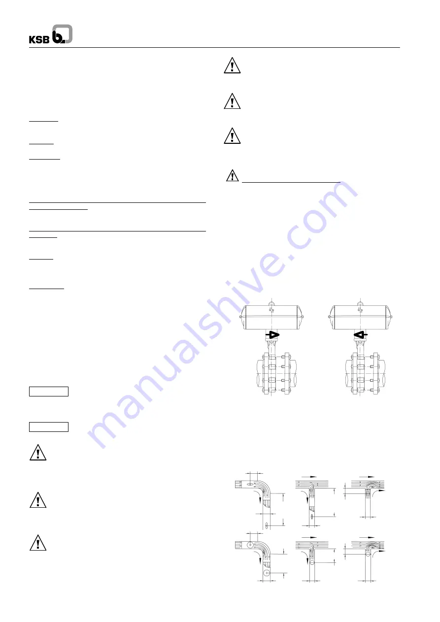
7.2.1.
Recommended minimum distances between
the position of the valve and of the T--piece or
elbow.
Ø
1
Ø
Ø
Ø
1
Ø
Ø
2--3
Ø
Ø
Ø
1
Ø
1
Ø
2--3
Ø
5--6
Ø
2--3
Ø
Also valid for valve placed at pump discharge


