GB-11
D
GB
F
NL
I
E
0
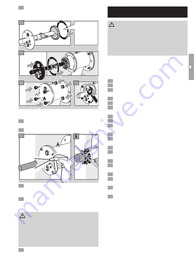
When the furnace chamber has cooled down,
check the burner tube and burner quarl through
the furnace flange.
22
23
24
21
New gas
housing
gasket.
▷
Tighten the burner insert with max. 37 Nm
(27.3 lb ft).
5
Connect the system to the electrical power sup-
ply.
6
Open the gas and air supply.
27
8
Set the burner to low fire and compare the pres-
sure settings to those stated in the acceptance
report.
9
Set the burner to low and high fire several times
while monitoring the pressure settings, flue gas
values and flame patterns.
DANGER
Risk of explosion and poisoning during burner
adjustment with an air deficiency!
Adjust the
gas and air supply so that the burner is always oper-
ated with excess air – otherwise CO will form in the
furnace chamber. CO is odourless and poisonous!
Conduct a flue gas analysis.
0
Produce a maintenance report.
Assistance in the event of
malfunction
DANGER
Electric shocks can be fatal! Before working on
possible live components, ensure the unit is discon-
nected from the power supply.
Risk of injury! Burner heads have sharp edges.
Fault-clearance must only be undertaken by author-
ized trained personnel.
▷
If no fault is detected when checking the burner,
proceed to the automatic burner control unit and
check for faults in accordance with the relevant
operating instructions.
?
Faults
!
Cause
•
Remedy
?
Burner does not function?
!
Valves do not open.
•
Check the voltage supply and wiring.
!
Tightness control signals a fault.
•
Check the valves for tightness.
•
Note the tightness control operating instructions.
!
Control valves do not move to low-fire position.
•
Check the impulse lines.
!
Gas inlet pressure is too low.
•
Check the filter for dirt.
!
Gas and air pressures on the burner are too low.
•
Check the restrictors.
!
Automatic burner control unit signals a fault.
•
Check the ionization cables and ionization cur-
rent.
•
Check whether the burner is adequately ground-
ed.
•
Note the automatic burner control unit operating
instructions.


