BIC · Edition 09.22
EN-13
1
2
3
➔
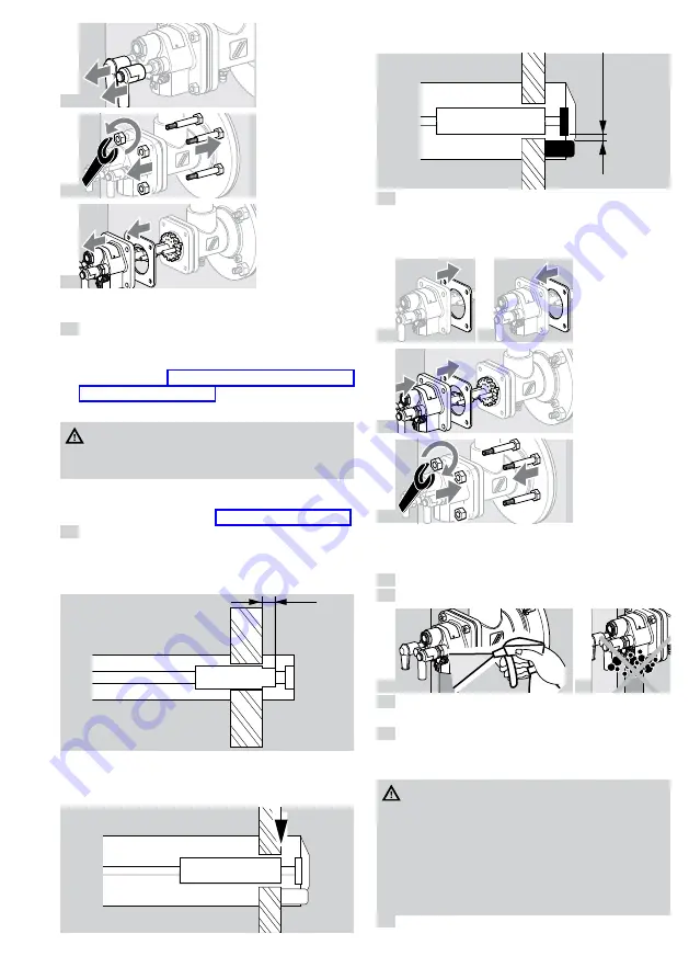
If the burner insert is dismantled, the gas housing
gasket will have to be renewed.
4
Place the burner insert in a safe place.
➔
Depending on the amount of dirt or wear: replace
the spark electrode/flame rod and dowel pin during
servicing – see page 12 (7.1 Checking the spark
electrode and flame rod).
➔
Check burner head for dirt and thermal cracks.
WARnInG
Risk of injury!
– Burner heads have sharp edges.
➔
When replacing any burner components: apply
ceramic paste to the screw connections in order to
avoid cold-setting – see page 14 (9 Accessories).
5
Check the electrode positions.
BIC..50
➔
The front part of the insulator must protrude 4 mm
from the burner air disc.
4 mm
BIC..65 to 140
➔
The insulator must be flush with the front edge of
the burner air disc.
➔
Distance of spark electrode from ground pin or gas
nozzle: 2 ± 0.5 mm (0.08 ± 0.02").
2
±
0,5
mm
(0.08
±
0.02
inch)
6
When the furnace chamber has cooled down,
check the burner tube and burner block through
the furnace flange.
➔
Replace the gas housing gasket.
7
8
9
10
➔
Tighten burner insert in a crosswise fashion: BIC(A)
50 to 100 with max. 15 Nm (11 lb ft), BIC 125 to
140 with max. 30 Nm (22 lb ft).
11
Connect the system to the electrical power supply.
12
Open the gas and air supply.
13
14
15
Set the burner to low fire and compare the pressure
settings to those stated in the acceptance report.
16
Set the burner to low and high fire several times
while monitoring the pressure settings, flue gas
values and flame patterns.
DAnGeR
Risk of explosion and poisoning in case of burner
adjustment with insufficient air!
– Adjust the gas and air supply so that the burner
is always operated with excess air – otherwise
CO will form in the furnace chamber. CO is
odourless and poisonous! Conduct a flue gas
analysis.
17
Produce a maintenance report.


