PFU 780 · Edition 02.12
64
F1
F2
A
B
C
D
E
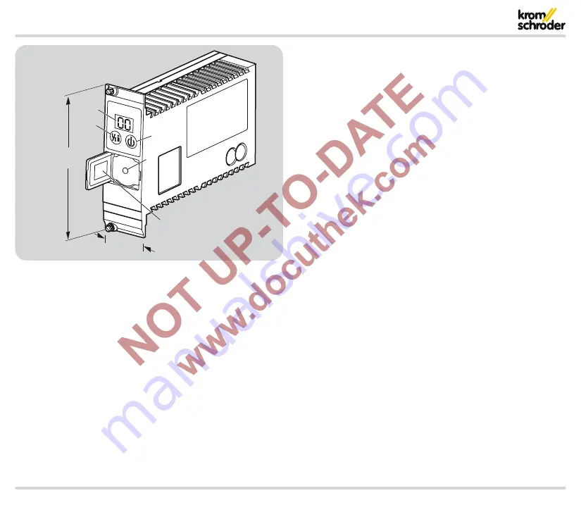
3 HE =
133.4 (5.3“)
8 TE =
40.6 (1.6“)
9 .2 Operating controls
A: 2-digit 7-segment display
B: Reset/Information button to reset the system after a fault
or to scan parameters on the display
C: Mains switch
D: Optical interface
E: Type label
Technical data


