


VAA · Edition 09.21
EN-5
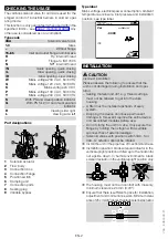
Bypass flow rate
10
0,3
0,5
1,5
3 4 5
7
50
30
70
100
150
200
1
2
10
20
30
0,2
0°
30°
40°
50°
60°
70°
80°
90°
20°
10°
4
11,9
18,7
187
19,7
11,8
27,6
39,4
59,1
78,7
37,3
74,7
373
747 1120
7,5
Q [m
3
/h (n)]
Q [SCFH]
p
u
[mbar]
p
u
[inch WC]
The characteristic flow rate curves have been meas-
ured with the valve closed.
The setting for the opening angle in the bypass de-
pends on the supply pressure and air requirement.
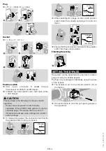
CoMMIssIonInG
setting the flow rate
➔
At the factory, the valve is adjusted for maximum
flow rate Q.
➔
The markings on the cover cap can be used for
coarse adjustment of the flow rate.
➔
The cover cap can be rotated without changing the
current flow rate.
➔
Allen key: 2.5 mm.
➔
Do not turn beyond the “max.” setting.
Q [%]
max.
min.
100
0
U
-
+
min.
max.
➔
The VAA remains tight even if the adjusting screw
is overturned.
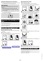
setting the start rate on the VAA../L
➔
The start rate can be set by turning the damping
unit a maximum of 5 turns.
➔
There must be a period of 20 seconds between
switching the valve off and on again so that the
damping is fully effective.
➔
Loosen the M5 setscrew (2.5 mm hexagon socket),
but do not unscrew completely.
1
2
3
Turn the damping unit clockwise to the zero setting/
as far as possible.
4
-
+
5
6
Screw the M5 setscrew back in.