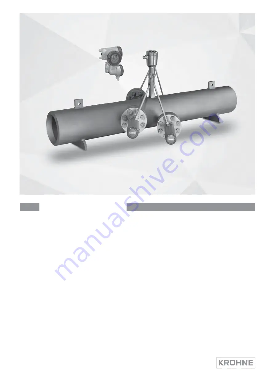
Ultrasonic flowmeterfor high-temperature gas and superheated steam
ER 1.1.7_
OPTISONIC 8300
Quick Start
© KROHNE 03/2020 - 4008065101 - QS OPTISONIC 8300 R01 en
Страница 1: ...er for high temperature gas and superheated steam ER 1 1 7_ OPTISONIC 8300 OPTISONIC 8300 OPTISONIC 8300 OPTISONIC 8300 Quick Start Quick Start Quick Start Quick Start KROHNE 03 2020 4008065101 QS OPT...
Страница 2: ...2 9 5 Thermal insulation 13 2 10 Mounting the field housing remote version 14 2 10 1 Wall mounting 14 2 10 2 Turning the display of the field housing version 15 3 Electrical connections 16 3 1 Safety...
Страница 3: ...se instructions can result in damage to the device or to parts of the operator s plant INFORMATION These instructions contain important information for the handling of the device CAUTION Installation...
Страница 4: ...in two different packagings The carton packaging contains the converter The flowmeter will be packed depending on size and weight on a wooden pallet protected with cardboard or in a wooden crate Make...
Страница 5: ...mpletely filled pipe line circuits Your measuring device is supplied ready for operation The factory settings for the operating data have been made in accordance with your order specifications The fol...
Страница 6: ...e 1 Name and address of the manufacturer 2 Ambient temperature 3 Ingress protection 4 Tag no 5 PED data 6 Calibration data 7 Type designation of the flowmeter and CE sign with number s of notified bod...
Страница 7: ...nt devices P passive mode external power supply required for operation of the subsequent devices N C connection terminals not connected Figure 2 5 Example of a nameplate for electrical connection data...
Страница 8: ...age temperature 50 70 C 58 158 F 2 5 Transport Signal converter Do not lift the signal converter by the cable glands Flow sensor Do not lift the flow sensor by the connection box transducers nozzles o...
Страница 9: ...or heat exchanger Do not expose the signal converter to intense vibrations and mechanical shocks Figure 2 7 Prevent intense vibrations INFORMATION In case of too many vibrations please install support...
Страница 10: ...not install the flow sensor in a lowered pipe section to avoid that water can collect in the measuring tube Orientate the flow sensor such that the path of the acoustic signal is in the horizontal pl...
Страница 11: ...3 2020 4008065101 QS OPTISONIC 8300 R01 en 2 9 3 Flange deviation CAUTION Max permissible deviation of pipe flange faces Lmax Lmin 0 5 mm 0 02 Figure 2 10 Flange deviation 1 Lmax 2 Lmin 2 9 2 T sectio...
Страница 12: ...in case of the presence of liquids and or in steam applications Horizontal or vertical installation position in case of dry gas In case of the presence of liquid or steam applications Figure 2 11 Hori...
Страница 13: ...ow ambient temperature electric heat tracing may be applied to prevent condensation and or to reduce startup time WARNING Keep the transducers and connection box free of insulation to allow cooling by...
Страница 14: ...ounting material and tools in compliance with the applicable occupational health and safety directives 3 Fasten the housing securely to the wall 4 Screw the signal converter to the mounting plate with...
Страница 15: ...Pull out the display and rotate it to the required position 3 Slide the display back into the housing 4 Re fit the cover and tighten it by hand Figure 2 16 Turning the display of the field housing ver...
Страница 16: ...e DANGER Observe the national regulations for electrical installations DANGER For devices used in hazardous areas additional safety notes apply please refer to the Ex documentation WARNING Observe wit...
Страница 17: ...nctioning always use the signal cable s included in the delivery Figure 3 2 Clamp the cables on the shielding bush 1 Cables 2 Cable glands 3 Grounding clamps 4 Cable with metal shielding bush Figure 3...
Страница 18: ...cuit breaker and wiring has to be suitable for the application and shall also be in accordance with the local safety requirements of the building installation e g IEC 60947 1 3 DANGER For devices used...
Страница 19: ...VAC DC tolerance range AC 15 10 DC 25 30 24 VAC DC tolerance range AC 15 10 DC 25 30 24 VAC DC tolerance range AC 15 10 DC 25 30 Note the data on the nameplate For measurement process reasons a functi...
Страница 20: ...th various output modules Current outputs can be active or passive Optionally available also with Foundation Fieldbus Modular version Depending on the task the device can be configured with various ou...
Страница 21: ...ay modular I O Ia Pa Sa and optional module Pp Sp Ip Abbreviation Identifier for CG no Description Ia A Active current output Ip B Passive current output Pa Sa C Active pulse output frequency output s...
Страница 22: ...ive Pp Sp passive 2 Ia HART active 1 Ex i I Os option 2 0 0 Ia HART active PN SN NAMUR 2 3 0 0 Ip HART passive PN SN NAMUR 2 2 1 0 Ia active PN SN NAMUR Cp passive 2 Ia HART active PN SN NAMUR 2 3 1 0...
Страница 23: ...Pa Sa active 1 8 _ _ max 2 optional modules for term A B Ip HART passive Pa Sa active 1 6 _ _ max 2 optional modules for term A B Ia HART active Pp Sp passive 1 B _ _ max 2 optional modules for term...
Страница 24: ...pecified as they will vary with each application The information below should therefore be regarded as indicative Dimensions of the OPTISONIC 8000 in mm and inches INFORMATION Please note size d the r...
Страница 25: ...nd weights in inches and lb 4 3 Mounting plate of field housing Figure 4 2 Field housing F remote version Dimensions mm Weight kg a b c d e 202 120 155 295 8 277 5 7 Dimensions inches Weight lb a b c...
Страница 26: ...power supply are correct Switching on the power 5 2 Starting the signal converter The measuring device consisting of the flow sensor and the signal converter is supplied ready for operation All opera...
Страница 27: ...ONIC 8300 R01 en 5 3 Menu overview Measuring mode Select menu Select menu and or sub menu Select function and set data Press 2 5 s A quick setup A1 language A2 tag A3 reset A3 1 reset errors A3 2 coun...
Страница 28: ...B1 _ status output X B2 actual values B2 1 act volume flow B2 2 act corrected flow 1 B2 3 act enthalpy flow 2 B2 4 act mass flow B2 5 act molar mass 1 B2 6 act specific enthalpy 2 B2 7 act density 2...
Страница 29: ...gs 1 C1 9 linearization C1 10 adiabatic index 2 C1 11 P T correction 2 C1 12 P T inputs 2 C1 13 pipe temperature 2 C1 14 pipe pressure 2 C1 15 density 2 C1 16 diagnosis value C2 I O input output C2 1...
Страница 30: ...C 8300 R01 en Measuring mode Select menu Select menu and or sub menu Select function and set data C setup C5 device C5 1 device info C5 2 display C5 3 1 meas page C5 4 2 meas page C5 5 graphic page C5...
Страница 31: ...NOTES 6 31 OPTISONIC 8300 www krohne com 03 2020 4008065101 QS OPTISONIC 8300 R01 en...
Страница 32: ...rvices Head Office KROHNE Messtechnik GmbH Ludwig Krohne Str 5 47058 Duisburg Germany Tel 49 203 301 0 Fax 49 203 301 10389 info krohne com KROHNE 03 2020 4008065101 QS OPTISONIC 8300 R01 en Subject t...