background image

2

 INSTALLATION 

14 

OPTIFLEX 1100 C

www.krohne.com

01/2012 - 4001226201 - QS OPTIFLEX 1100 R01 en

2.4  How to install a device with a threaded connection

Equipment needed:

Gasket (not supplied with G (ISO 228) threaded connections)

34 mm wrench (not supplied)

2.5  How to turn or remove the signal converter

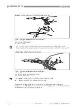
How to remove the signal converter

•  

Loosen the lock screw with a 5 mm wrench.

•  

Remove the signal converter from the probe assembly.

•  

Put the cover 

3

 on the probe assembly.

Figure 2-14: How to turn or remove the signal converter

1  

Signal converter

2  

Process connection and probe assembly

3  

Cover for the coaxial hole on top of the  process connection assembly

CAUTION!

When the housing is attached to the process connection assembly, make sure that the lock 
screw is tight.

Содержание OPTIFLEX 1100 C

Страница 1: ...Guided Radar TDR Level Meter OPTIFLEX 1100 C OPTIFLEX 1100 C OPTIFLEX 1100 C OPTIFLEX 1100 C Quick Start Quick Start Quick Start Quick Start KROHNE 01 2012 4001226201 QS OPTIFLEX 1100 R01 en...

Страница 2: ...ns 6 2 2 1 Scope of delivery 6 2 2 2 How to assemble the segmented coaxial probe 7 2 3 4 mm 0 15 single cable probe solid applications 11 2 3 1 Scope of delivery 11 2 3 2 How to assemble a single cabl...

Страница 3: ...operator s plant INFORMATION These instructions contain important information for the handling of the device CAUTION Installation assembly start up and maintenance may only be performed by appropriate...

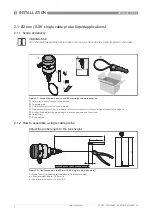
Страница 4: ...ngle cable probe option 1 Converter process connection and probe 2 Counterweight 3 2 HC M6 5 screws for the counterweight 4 Probe assembly cover For more data refer to How to turn or remove the signal...

Страница 5: ...e is prepared for installation on the tank If you decreased the probe length you must enter the new value in the device configuration menu NOTE the device must have the LCD display option or the HMI s...

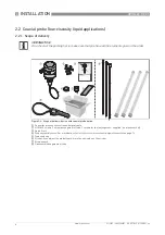
Страница 6: ...er Figure 2 4 Scope of delivery device with coaxial probe option 1 Converter process connection and signal cable 2 HC M6 5 screws 1 screw per segment of tube 3 screws for the last segment supplied in...

Страница 7: ...ch the lock screw to the top of the tube Tighten with a 3 mm Allen wrench Do these steps again for each segment of tube but do not attach the lock screw to the last segment of tube Attach the tube seg...

Страница 8: ...segments attached but without the probe end cap b Length of tube needed total probe length L 15 mm 0 6 1 Coaxial probe Last segment of the tube 2 Do not attach the lock screw to the last segment of t...

Страница 9: ...3 mm Allen wrench Adjust the probe length to the tank height Figure 2 7 How to assemble the segmented coaxial probe 1 Coaxial probe Last segment of the tube 2 Probe end cap 3 1 HC M6 5 lock screw 4 Bo...

Страница 10: ...d the probe length you must enter the new probe length in the device configuration menu NOTE the device must have the LCD display option or the HMI service tool For more data refer to Quick Setup on p...

Страница 11: ...ll the elements given in the order Figure 2 10 Scope of delivery device with 4 mm single cable probe option 1 Converter and process connection 2 Counterweight 3 4 HC M6 5 screws for the counterweight...

Страница 12: ...the probe 2 Attach the union nut 4 to the fitting at the top of the probe Use two 8 mm wrenches to tighten the lock nut and union nut Use the union nut to attach the probe to the fitting below the pr...

Страница 13: ...robe length you must enter the new probe length in the device configuration menu NOTE the device must have the LCD display option or the HMI service tool For more data refer to Quick Setup on page 16...

Страница 14: ...ignal converter How to remove the signal converter Loosen the lock screw with a 5 mm wrench Remove the signal converter from the probe assembly Put the cover 3 on the probe assembly Figure 2 14 How to...

Страница 15: ...tment cover Figure 3 1 How to open the terminal compartment cover Connect the device to the electrical circuit Figure 3 2 How to connect the device to the electrical circuit WARNING If you do not push...

Страница 16: ...rent output percentage bar graph and text only shown if the output function is the same as the measurement name on the screen in normal mode 2 Measurement name in this example distance 3 Device tag na...

Страница 17: ...or Conversion is set the 0 limit for the 4 20 mA scale is at the bottom of the tank If Distance or Ullage Conv is set the 0 limit is at the top of the tank to change Scale 4 mA to change the position...

Страница 18: ...5 NOTES 18 OPTIFLEX 1100 C www krohne com 01 2012 4001226201 QS OPTIFLEX 1100 R01 en...

Страница 19: ...NOTES 5 19 OPTIFLEX 1100 C www krohne com 01 2012 4001226201 QS OPTIFLEX 1100 R01 en...

Страница 20: ...s products Measuring systems for the oil and gas industry Measuring systems for sea going tankers Head Office KROHNE Messtechnik GmbH Ludwig Krohne Str 5 D 47058 Duisburg Germany Tel 49 0 203 301 0 Fa...

Отзывы: