background image

Supplementary Documentation 

Page 4 of 44 

IFC090, IFC090 i with FF 

Introduction 

IFC090 FF 01/2005


KROHNE Messtechnik GmbH & Co. KG · Ludwig-Krohne-Str. 5 

‚

 D-47058 Duisburg 


Tel.: 0203-301 309 

‚

 Fax: 0203-301389 · E-mail: [email protected] 

1 Introduction 

These instructions are supplementary to the “Installation and Operating Instructions IFC 090 K / F“. The details 

depicted therein, in particular the Safety Information are valid and should be adhered to. The present 

Supplementary Instructions provide additional information for the devices when being operated and connected 

to a Foundation Fieldbus.  

Note: Please set the controller to manual mode before changing parameters of the IFC 090. 

The present Supplementary Instruction for the IFC 090 with Foundation Fieldbus- interface, plus a diskette with 

the DD and CCF file are included in our scope of supply, in addition to those items delivered for the standard 

device. 


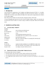
2  Installation and Operation 

2.1 

Technical Data  IFC090 FF 

Hardware 

Physical 


to IEC 61158-2 and the FISCO model 

Bus characteristics: 


9... 30 V; 0.3 A max.; 4.2 W max. 

Base current 


10 mA 

FDE 


bus with separate fault detection electronics  

Fault current  


6 mA; (fault current = max. continuous current – base current) 

Starting current 


lower than the base current 

“Ex“ approval 


EEx ia IIC T6 or EEx ib IIC/IIB T6 in conformity with the FISCO model 

Connection   


independent of polarity 


Software 

DD, CFF File 


supplied on diskette, available also in the KROHNE Downlaod Center 

Functional blocks   


flow [m3/s], integrator 1 [m3], integrator 2 [m3]; units are default units 

Operator control    


local display and operator interface at device 


2.2 Electrical 

Connection 

of Foundation Fieldbus Devices  

Connect the bus cable as shown in the figure.  

  Connect the cable cores to terminals D and DI.. Polarity reversal will not have any effect. 

  The cable shield should be connected with minimum length to the FE functional ground. 

  The equipotential bonding conductor must be connected to the device by connecting it to FE functional 

ground. 


Содержание IFC 090

Страница 1: ...esstechnik GmbH Co KG Ludwig Krohne Str 5 D 47058 Duisburg Tel 0203 301 309 Fax 0203 301389 e mail krohne krohne de Supplementary Installation and Operating Instructions IFC 090 IFC 090 i With FOUNDAT...

Страница 2: ...low 16 4 4 Integrator Blocks 1 and 2 Flow and Flow Totalizer 22 5 IFC090 FF Configuration 28 5 1 Resource Block Configuration 28 5 1 1 Resource Block Mode Handling 28 5 1 2 Write Protection 28 5 1 3 R...

Страница 3: ...o KG Ludwig Krohne Str 5 D 47058 Duisburg Tel 0203 301 309 Fax 0203 301389 E mail krohne krohne de 6 Troubleshooting 42 6 1 BLOCK_ERROR 42 6 1 1 Resource Block 42 6 1 2 Transducer Block 42 6 1 3 Analo...

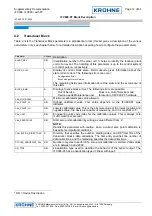
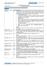
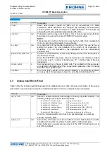
Страница 4: ...device 2 Installation and Operation 2 1 Technical Data IFC090 FF Hardware Physical to IEC 61158 2 and the FISCO model Bus characteristics 9 30 V 0 3 A max 4 2 W max Base current 10 mA FDE bus with sep...

Страница 5: ...the FISCO model even the termination the maximum cable length should not exceed 1000 m the values of the cable are within the following ranges R 15 150 km L 0 4 1mH km C 80 200nF km other limitations...

Страница 6: ...d shielded cables is strongly recommended otherwise EMC protection of the IFC 090 cannot be assured 2 5 IFC090 Menu Settings for Foundation Fieldbus see also Section 4 in the Installation and Operatin...

Страница 7: ...inction is made between the following kinds of blocks see Figure 1 Resource Block Transducer Block s and Function Block s Figure 1 Foundation Fieldbus block scheme 3 1 Resource Block Each FF device po...

Страница 8: ...information in terms of sensor actuator functions e g type of sensor range of process value etc and they make available the process values to the function blocks or provide the actuator input values o...

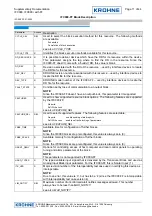
Страница 9: ...9 Fax 0203 301389 E mail krohne krohne de 4 IFC090 FF Block Description The IFC090 FF consists of the following blocks see figure 2 1 Resource Block 1 Transducer Block standard flow 1 Analog Input Blo...

Страница 10: ...ch is the only writable field of this parameter can be used to disable these alarms see also ACK_OPTION ALERT_KEY R W ALERT_KEY parameter contains the identification number of the plant unit It helps...

Страница 11: ...block this parameter isn t supported FEATURES R Used to show supported resource block options The following features are supported by the IFC090 FF Reports Soft Write Lock see also FEATURE_SEL FEATUR...

Страница 12: ...s the Resource Block does NOTE Under certain conditions e g RS_STATE ONLINE_LINKING the Resource Block is not capable of switching to AUTO mode see also RS_STATE NV_CYCLE_T R Minimum time interval bet...

Страница 13: ...e in setting this value The only limitation is the length of 32 characters at maximum It is not checked by the application but has informational character only TEST_RW R W Read write test parameter It...

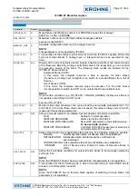
Страница 14: ...ervice block is in Out of Service mode Device needs Maintenance now fatal error of IFC090 FF hardware CAL_MIN_SPAN R Minimum calibrated span value allowed CAL_POINT_HI R W Highest calibrated value Thi...

Страница 15: ...its code and the number of digits to the right of the decimal point to be used to display the PRIMARY_VALUE PRIMARY_VALUE_TYPE R W Type of sensor The IFC090 FF is of type volumetric flow 101 NOTE Even...

Страница 16: ...of transducers 711 starting index of the only transducer UPDATE_EVENT R Alert generated by a change to static data The subfields of this parameter give detailed information about the changed static p...

Страница 17: ...formation about the state and the occurrence of this alarm BLOCK_ERR R Display of active block errors The following errors are possible Out of Service block is in Out of Service mode Input Failure SIM...

Страница 18: ...evaluated 1 exceeding of high limit is been evaluated but acknowledgement isn t necessary 2 7 exceeding of high limit is been evaluated and reported according to the given priority 2 low priority 7 hi...

Страница 19: ...ported according to the given priority 2 low priority 7 high priority Status of OUT changes to Good NC UnackAdvisoryAlarm LowLimited 8 17 exceeding of low limit is been evaluated and reported accordin...

Страница 20: ...ult of executing the block In Auto mode of this block the value and its status is automatically calculated on the base of the channel value obtained from the Transducer Block and calculation methods o...

Страница 21: ...cal value NOTE This parameter is neither checked nor used by the function block application It can be used by control system to group blocks TAG_DESC R W User description of the intended application o...

Страница 22: ...alizer unless expressively pointed out Figure 2 IFC090 FF Integrator Block Parameter Access Description ALERT_KEY R W ALERT_KEY parameter contains the identification number of the plant unit It helps...

Страница 23: ...be considered in the totalization status to be considered in the totalization and if the totalizatiion residue shall be used in the next batch after a reset The following INTEG_OPTS are possible Input...

Страница 24: ...desired target possible permitted and normal modes of the Integrator Block By writing a permitted value to the target field you can control the execution modes of the block The following block modes a...

Страница 25: ...termine the status of the output value OUT It is calculated by the following equation PCT_INCL 100 1 rtotal atotal where rtotal is the portion of BAD and Uncertain net flows and atotal the absolute va...

Страница 26: ...rameter PCL_INCL see PCL_INCL for details see also PCL_INCL SRTOTAL R SRTOTAL stands for snapshot RTOTAL and displays the value of RTOTAL just before the last reset if one has happened inspect N_RESET...

Страница 27: ...aning depends on the chosen type of integration see INTEG_TYPE for details see also INTEG_TYPE UNCERT_LIM R W UNCERT_LIM specifies the limit for Uncertain status of parameter OUT If PCT_INCL gets belo...

Страница 28: ...ate and perform their functional tasks In the Out of Service mode all other blocks are in Out of Service mode too and are not capable of changing their mode unless the Resource block is set to to Auto...

Страница 29: ...lized with respect to saved configuration ONLINE LINKING In this state all parameters are initialized and the device is waiting for the links are all established STANDBY This state reflects that all i...

Страница 30: ...ransducer Block freezes its measurement value to the last one obtained in Automatic mode and sets its status to BAD OutOfService NonSpecific If the block is in Out of Service mode this is also indicat...

Страница 31: ...ock input value The value received over this channel is the base of the measurement value processing Since the Transducer Block of the IFC090 FF consists of one channel only the Analog Input block par...

Страница 32: ...abilize the flow as indicated in the display see section 6 4 and 6 5 of the IFC090 Installation and Operating Instruction The flow input value for the FF module is based on that smoothed flow value in...

Страница 33: ...downstream devices could be damaged or a low limit that may not be remain below otherwise the production process is in danger to be interrupted For these purposes the Fieldbus Foundation specified th...

Страница 34: ...surement deliverance is active Manual Man The block doesn t perform an automatic deliverance of valid measurement values but freezes the measurement processing to the last value obtained in Automatic...

Страница 35: ...r UNIT_CONV to the appropriate value Example Accumulation input The inputs of IN_1 and IN_2 are numbers of pulses Since the integration process operates with a quantity unit it has to be specified for...

Страница 36: ...w reverse are disabled set to false 5 4 5 Type of Integration The IFC090 FF integrators support the following seven Fieldbus Foundation specified integrator types which can be selected in parameter IN...

Страница 37: ...Reset Reference point is the value of TOTAL_SP If the totalization i e the OUT value exceeds TOTAL_SP it is reset to zero 0 0 A snapshot of the value at which the reset happened is saved in parameter...

Страница 38: ...the only possibilities to cause a totalization reset Periodic Demand This combines the reset possibilities of settings Periodic and Demand i e time based and operator resets are possible Normally the...

Страница 39: ...reset occurs the conditions that set OUT_PTRIP and OUT_TRIP are no longer true so they are cleared In any case OUT_TRIP is set for at least 5 seconds even if a reset happened From this the control sys...

Страница 40: ...5 D 47058 Duisburg Tel 0203 301 309 Fax 0203 301389 E mail krohne krohne de input status Good value is used for the integration input status Uncertain value of last input with Good status is used ins...

Страница 41: ...e calculation of RTOTAL isn t affected by this setting i e the value is used for the integration but even though the input is interpreted as Bad and added to RTOTAL Use Bad Status of input values of I...

Страница 42: ...t electronics NOTE Not the bus power This requires an action at the device s display Quit the ERROR QUIT menu at the device s display Refer to the Installation and operating instructions Signal conver...

Страница 43: ...n be read from the Analog Input Block parameter OUT status The following table lists almost all of the Analog Input OUT statuses that are mapped to IFC090 Precondition Analog Input Block is configured...

Страница 44: ...ameter PRIMARY_VALUE the raw measurement value obtained from the device can provide further information on possible reasons for measurement problems The following table lists possible indications PRIM...

Отзывы: