


1/4
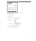
Stripping (preparation) of signal cable A 1.3.3
Please note the different lengths given in the table for signal converter and primary head.
Length Converter
Primary
head
mm
(inch)
mm
(inch)
a
55
(2.17) 90
(3.60)
b
10
(0.39)
8
(0.30)
c
15
(0.59) 25
(1.00)
d
8
(0.30)
8
(0.30)
Customer-supplied materials
W Insulation tubing (PVC), Ø 2.0 - 2.5 mm (dia. 1”)
X Heat-shrinkable tubing or cable sleeve
Y Wire end sleeve to DIN 41 228: E 1.5-8
Z
Wire end sleeve to DIN 41 228: E 0.5-8
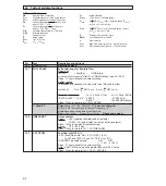
External shielding of signal cable A (Type DS)
Wrap stranded drain wire (7) around the mu-metal foil (6) and clamp under the shield terminal in
the signal converter terminal box (see also diagram in Sect. 1.3.5).
Cable routing in signal converter housing
see illustration in Sect. 10.4.
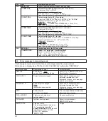
Preparation for connection to primary head
Preparation for connection to IFC 010 F signal converter
Signal cable A
bending radius
≥
50 mm (
≥
2“)
Signal cable A
bending radius
≥
50 mm (
≥
2“)