


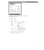


• All operating data and functions can be set:
Display version:
IFC 010 D, see Sect. 4 and 5.7, Fct. 1.06 for operator control
Basic version:
IFC 010 B, see Sect. 6.1 for operator control
• The pulse and status outputs can be operated in the active or passive mode.
Active mode:
The current output is the internal voltage source,
connection of electronic totalizers (EC)
Passive mode:
External DC or AC voltage source required, connection of electronic (EC)
or electromechanical (EMC) totalizers
• Digital pulse division, interpulse period is non-uniform. Therefore, if frequency meters or
cycle counters are connected, allow for minimum counting interval:
gate time, counter
≤
1000
P
100%
[ Hz]
• Connection diagrams see Sect. 2.3: diagrams - pulse output 3 4
diagrams - status output 5 6
2/1
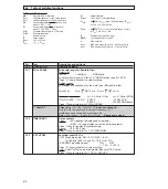
2.1 Current output I
•
The current output is galvanically isolated from all input and output circuits.
•
Factory-set data and functions can be noted down in Sect. 5.16.
Please also refer to Sect. 3.2 “Factory settings”.
•
Typical current output
•
All operating data and functions can be set.
•
Display version: IFC 010 D, see Sect. 4 and 5.6, Fct. 1.05 for operator control
Basic version: IFC 010 B, see Sect. 6.1 for operator control
•
The current output can also be used as an internal voltage source for the outputs.
U
int
= 15 V DC I = 23 mA when operated without receiver instruments at the current output
I = 3 mA when operated with receiver instruments at the current output
•
Connection diagrams, see Sect. 2.3: diagrams 1 2 4 6
I+ approx. 15 V DC positive
voltage of current output
I current sink
I
⊥
chassis ground, current output
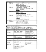
2 Electrical connection of outputs
2.2 Pulse output P and status output S
• The pulse and status outputs are galvanically isolated from the current output and all input circuits.
• Factory-set data and functions can be noted down in Sect. 5.16.
Please also refer to Sect. 3.2 “Factory settings”.
• Typical pulse and status outputs B1
S status output
P
⊥
⊥
chassis ground
P pulse output