11
5 Installation
notes
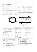
Inlet run:
• downstream of a compressure or nozzle
≥
40 x DN
• downstream of a fan
≥
30 x DN
• downstream of fully open control valve
≥
20 x DN
• downstream of a 90° bend (elbow)
≥
20 x DN
• downstream of a reducer (
α
/2 < 4°)
no additional inlet run required
Outlet run:
≥
10 x DN (DN = meter size)
Installation
conditions
Select position such that the measuring beam is approximately horizontal.
Fit the mating flanges precisely at right angles to the pipeline.
6.1 Electrical
connection
• Power supply, power consumption and load rating
of outputs, see “Technical data”
• Current and pulse outputs (I + P) are galvanically
isolated
from all input and output circuits.
•
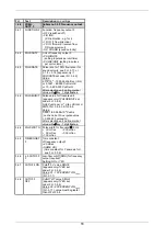
Selection of connection diagrams
Standard operation
EEx operation
Current output
2) passive/active
1) active (also standard)
Pulse output
3) passive
4) passive (also standard)
Power supply and connection terminals
5)
6)
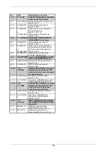
1) Current output
active
Standard
and
EEx
R
i
≤
680
Ω
2) Current output
passive
Standard
U
ext.
≤
18 V DC
R
i
≤
680
Ω
3) Pulse output
active
Standard
U
Output
= 19 V
−
32 V
R1
≥
650
Ω
I
≤
50 mA
EC
electronic totalizer
4) Pulse output
passive
Standard
and
EEx
U
ext.
≤
32 V DC
≤
24 V AC
I
≤
150 mA
EC
electronic totalizer
EMC
electromechanical
totalizer
5) Power supply connection
and all outputs
standard
L
N
L~ L~
only internal protective conductor
connection terminal
6) Power supply connection
and all outputs
EEx
version
L N
L~
L~
power supply
protective conductor
terminal
6.2 Electrical installation to the mains supply voltage
The GFM 700 is intended for permanent connection to the mains. It is required (for example for service) to mount an
external switch or circuitbreaker near the product for disconnection from the mains. It must be reached easily by the
operator and marked as the disconnecting device for this product. The switch or circuitbreaker has to be suitable for the
application and shall also be in accordance with local (safety) requirements and requirements of the building installation.
The protective conductor clamp terminal size M5, press-fitted, in the terminal compartment (Inear the power connection
terminals) shall always be connected to the protective earth conductor of the main supply. Conductors up to 4mm
2
can be
connected.
The diameter of the conductors of the main supply, including the protective earth conductor shall to be in accordance with
the general requirements.
binary
outputs
current
output
binary
oututs
current
output
Содержание GFM 700 F
Страница 31: ...31 9 ATEX approvals 9 1 GFC 700 F EEx Signal converter...
Страница 32: ...32...
Страница 33: ...33...
Страница 34: ...34 9 2 GFS 700 F EEx Primary head flowmeter...
Страница 35: ...35...
Страница 36: ...36...


