6
5. Connections
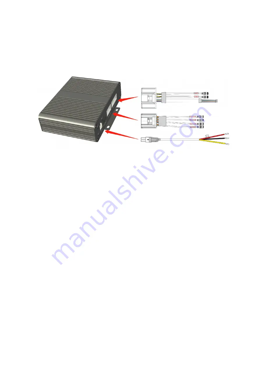
Connect the Power cable to the DC Power Input connector.
Connect the Camera input cable to the Camera input connector.
Connect the Video output & Trigger cable to the Video output & Trigger connector.
Power cable:
(1) Connect red wire to power wire of DC: 10-32V.
(2) Connect yellow wire to power wire of DC: 10-32V.
(3) Connect black wire to GND.
Camera input cable:
(1) Connect 4Pin male connector with label “Left CAM” to camera 1.
(2) Connect 4Pin male connector with label “Right CAM” to camera 2.
(3) Connect 4Pin male connector with label “Front CAM” to camera 3.
(4) Connect 4Pin male connector with label “Rear CAM” to camera 4.
Video output & Trigger cable:
(1) Connect white trigger wire to positive power wire of Camera 1.
(2) Connect blue trigger wire to positive power wire of Camera 2.
(3) Connect green trigger wire to positive power wire of Camera 3.
(4) Connect brown trigger wire to positive power wire of Camera 4.
(5) Connect both ends of the video amplifier cable of the 4-pin male connector labeled
"ECU-AHD" to the host computer and the AHD monitor, respectively.
(6) Connect 4Pin male connector with label “CVBS” to SD monitor.


