40
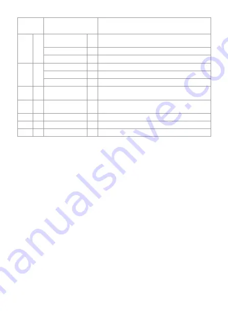
Gas group
Nominal connection
pressure
Destination
I
3B/P
30 mbar, G30
BE, CY, DK, EE, FR, GB, GR, HU, HR, IT, LT, NL, NO, RO, SE,
SI, SK, TR
37 mbar, G30
PL
50 mbar, G30
AT, CH, DE, FR, SK
I
3P
30 mbar, G31
FI, NL, RO
37 mbar, G31
BE, CH, CZ, ES, FR, GB, GR, HR, IE, IT, LT, NL, PL, PT, SI, SK
50 mbar, G31
AT, CH, DE, NL, SK
I
3+
28-30/37 mbar,
G30/G31
BE, CH, CY, CZ, ES, FR, GB, GR, IE, IT, LT, PT, SI, SK, TR
I
2H
20 mbar, G20
AT, CH, CY, CZ, DK, EE, ES, FI, GB, GR, HR, IE, IT, LT, LU, LV,
NO, PT, RO, SE, SI, SK, TR
I
2H
25 mbar, G20
HU
I
2E
20 mbar, G20
DE, PL, RO
I
2L
25 mbar, G25
NL
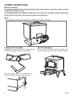
Set components
Please make sure that the set components were not damaged during transport. The inspection
should be carried out in the presence of the fitter. Before installing the stove, please learn all of the
elements that came with the device. In the case of any damage or omissions, please contact custo-
mer service. The user receives a set including:
• GV60M1 Mertik Maxitrol controller.
• B6R-R8U Mertik Maxitrol receiver.
• 8 - symbol B6R-H8T5B remote control.
• Clamp connector 8 mm.
• Clamp connector 6 mm.
• One-piece clamp connector 6 mm.
• Screw plus 3/8’’ - 2 pcs.
• G60-ZUS09 interrupter block.
• Control burner block G30-ZP2M.
• Control burner nozzle - NG (number 27_2) LPG (designation 22)
• Seal under the control burner block.
• Thermocouple G30-ZPT1500A.
• Magneto wire.
• Cables connecting the interrupter block with the receiver.
• An 8-core cable connecting the gas controller with the receiver.
• Reducing nipple 1/2 ‚’ to 3/8 ‚’.
• Gas connection cables having a diameter of 6 and 8 mm.
• Distribution box.
• Power module G60-ZBE (Option).
Содержание KOZA AB GAZ
Страница 4: ...4 Rys 1 KOZA AB GAZ zasilana gazem Rys 2 Wymiary gazowego ogrzewacza pomieszcze KOZA AB GAZ...
Страница 39: ...39 Rys 1 KOZA AB GAZ gas stove Rys 2 Dimensions Freestanding STOVE AB S EN...
Страница 47: ...47 Figure 10 Removal of the doors Figure 9 Removal of the bottom cover...
Страница 50: ...50 Fig 12 How to install a settler if required...
Страница 72: ......
Страница 74: ...74 Fig 1 KOZA AB GAZ gaz Fig 2 Dimensions du chauffage gaz KOZA AB GAZ...