


KRAMER: SIMPLE CREATIVE TECHNOLOGY
Operating the VP-727
28
9.1.1.1
Preview / Program Setting Output Test Pattern Screens
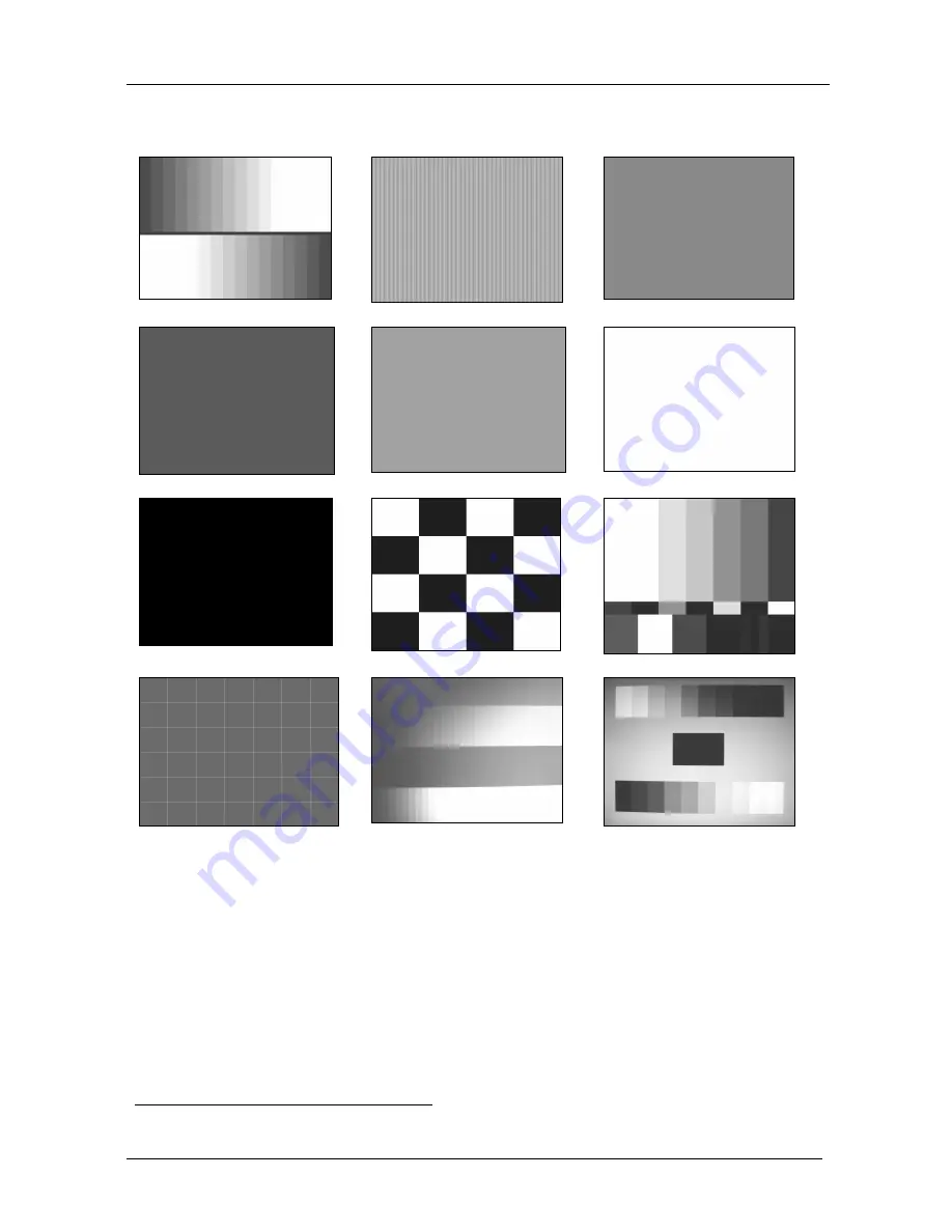
Figure 12 illustrates the Test Pattern screens
1
:
32 Gray Ramp
Sharpness
Red
Green
Blue
White
Black
Chessboard
Color Bar
Aspect Ratio
RGB Gray Ramp
Gamma Check
Figure 12: Test Pattern Screens
1 When selected, the test pattern is displayed after exiting from the OSD menu


