background image


VP-28 - Operating the VP-28 Remotely 

19 


Operating the VP-28 Remotely  

You can operate the 

VP-28

 remotely using the 

VP-28

 Controller Software via 

either the RS-232 serial port or the Ethernet port. 

The VP-28 Application Software can be downloaded from 

http://www.kramerelectronics.com

.  

The Controller Software requires the following: 


Windows™ XP, Vista or Windows™ 7 


Microsoft .Net Framework version 3.5 

To install the Controller Software, download the software and run the setup file. 

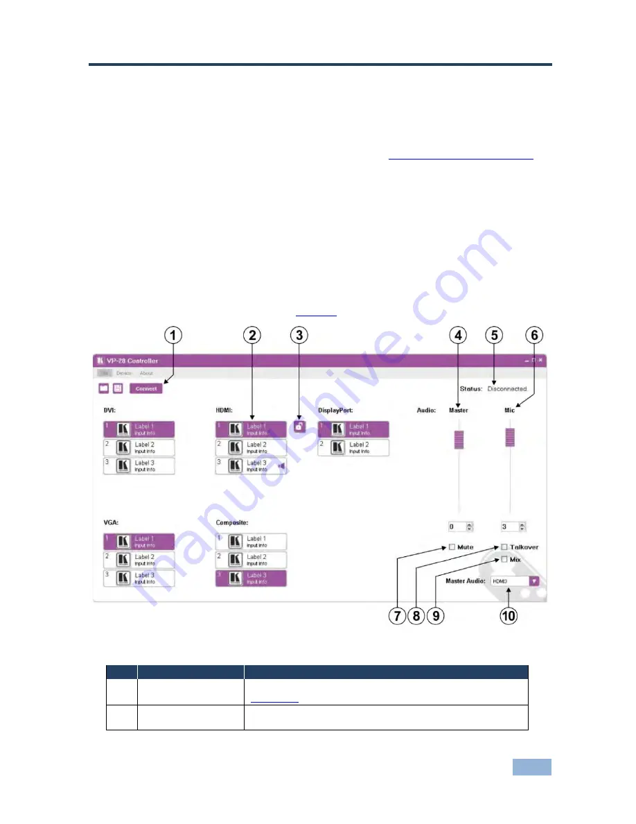
After installation, running the Controller Software for the first time displays a 

window similar to that shown in 

Figure 8

.  


Figure 8: Controller Software Main Window  


Feature 

Function 

Connect/Disconnect 

Button 


Click to connect to or disconnect from the device (see  

Section  7.2

)  

Select Input Buttons 


Click one of the 14 input buttons to select an input. The 
selected input button is highlighted  

Содержание VP-28

Страница 1: ...KRAMER ELECTRONICS LTD USER MANUAL MODEL VP 28 Presentation Switcher P N 2900 300080 Rev 3 ...

Страница 2: ......

Страница 3: ...Master Audio Switching Group 16 6 3 Locking the Front Panel 17 6 4 Resetting the VP 28 to the Factory Default 18 7 Operating the VP 28 Remotely 19 7 1 The Controller Software Menu Bar 21 7 2 Connecting to the Device 21 7 3 Switching an Input to the Output of the Group 22 7 4 Selecting a Master Audio Input 22 7 5 Operating the Combined 5 x 1 HDMI DP Switching Group 23 7 6 Changing the Audio Levels ...

Страница 4: ...ereo Audio Connection 15 Figure 7 Unbalanced Stereo Audio Connection 15 Figure 8 Controller Software Main Window 19 Figure 9 Typical Input Button 20 Figure 10 Connection Method Window 21 Figure 11 Input Selection 22 Figure 12 Master Audio Input Selection 22 Figure 13 Combine Button 23 Figure 14 Combined HDMI and DP Inputs 23 Figure 15 Changing the Audio Levels 24 Figure 16 Muting Audio and Selecti...

Страница 5: ... in 11 groups that are clearly defined by function GROUP 1 Distribution Amplifiers GROUP 2 Switchers and Routers GROUP 3 Control Systems GROUP 4 Format Standards Converters GROUP 5 Range Extenders and Repeaters GROUP 6 Specialty AV Products GROUP 7 Scan Converters and Scalers GROUP 8 Cables and Connectors GROUP 9 Room Connectivity GROUP 10 Accessories and Rack Adapters and GROUP 11 Sierra Video Pr...

Страница 6: ... programs and to check if firmware upgrades are available where appropriate 2 1 Achieving the Best Performance To achieve the best performance Use only good quality connection cables to avoid interference deterioration in signal quality due to poor matching and elevated noise levels often associated with low quality cables Do not secure the cables in tight bundles or roll the slack into tight coil...

Страница 7: ...pendently and that would otherwise require several separate products The VP 28 features 23 selector switches and front panel control adjustments for master audio output level and microphone level mix talk over and mute functions Support for up to 2 25Gbps bandwidth per graphic channel HDMI DVI Supports 1 to 4 data pairs lanes at a transfer rate of either 1 6Gbps or 2 7Gbps device dependent per cha...

Страница 8: ...set top box DVD player or A V receiver and video monitor such as a digital flat LCD plasma television DTV over a single lengthy cable SIMPLICITY With video and multi channel audio combined into a single cable the cost complexity and confusion of multiple cables currently used in A V systems is reduced LENGTHY CABLE HDMI technology has been designed to use standard copper cable construction at up t...

Страница 9: ...e video signal red green blue for a total of 24 bits per pixel The fourth link carries the pixel clock Each TMDS link carries binary data at ten times the pixel clock reference frequency for a maximum data rate of 1 65Gbps 3 data pairs for single link DVI The DVI specification mandates a maximum pixel clock frequency of 165MHz when running in single link mode With a single DVI link the highest sup...

Страница 10: ...ovides a simple interface between a PC and a display projector or TV Supports 1 to 4 data pairs lanes at a transfer rate of either 1 6Gbps or 2 7Gbps device dependent Has a maximum length of 15m 49ft for video transmission at a resolution of 1080p 60Hz and 3m 9 8ft for full bandwidth transmission Video specs include a video path that supports 6 to 16 bits per color channel a maximum resolution of ...

Страница 11: ...kind of monitor is connected to the output The EDID includes the manufacturer s name the product type the timing data supported by the display the display size luminance data and for digital displays only the pixel mapping data EDID is defined by a standard published by the Video Electronics Standards Association VESA 3 6 Defining the VP 28 Presentation Switcher Figure 1 defines the front panel of...

Страница 12: ...elect the MIC input as the primary audio feed and to lower the background Master audio level toggle 10 LOCK Button Press and hold to lock the front panel buttons Press and hold again to unlock the buttons 11 MASTER VOLUME Knob Turn to adjust the master audio level 12 MIC VOLUME Knob Turn to adjust the microphone audio level 13 MIC IN 6 5mm Microphone Jack Connect a microphone Note Only one microph...

Страница 13: ...Connect to the balanced stereo master audio acceptor see Section 5 3 27 DP AUDIO 3 5mm Mini Jack Connectors IN 1 IN 2 OUT Connect to the audio channel of the DP sources and acceptor 28 PC AUDIO 3 5mm Mini Jack Connectors IN 1 IN 3 OUT Connect to the audio channel of the PC graphics sources and acceptor 29 DVI AUDIO 3 5mm Mini Jack Connectors IN 1 IN 3 OUT Connect to the audio channel of the DVI so...

Страница 14: ...10 VP 28 Installing the VP 28 in a Rack 4 Installing the VP 28 in a Rack This section provides instructions for rack mounting the unit ...

Страница 15: ...our VP 28 connect its power and then switch on the power to the other devices Figure 3 Connecting the VP 28 Presentation Switcher To connect the VP 28 as illustrated in the example in Figure 3 1 Connect a microphone to the MIC IN XLR connector 2 Connect a composite video source for example a composite video player to the VIDEO IN 1 RCA connector i ...

Страница 16: ... OUT 3 5mm mini jack connector to an unbalanced stereo audio acceptor for example a power amplifier 9 Connect a DVI source for example a computer to the DVI IN 1 connector Note Using the Kramer ADC DM DF GF combined cable increases the input options available to you 10 Optional Connect a PC via Ethernet over a LAN to the Ethernet RJ 45 connector to control the VP 28 5 1 Connecting a Serial Control...

Страница 17: ...work hub or network router http www kramerelectronics com 5 2 1 Connecting the Ethernet Port directly to a PC You can connect the Ethernet port on the VP 28 to the Ethernet port on your PC via a crossover cable with RJ 45 connectors This type of connection is recommended for identification of the factory default IP Address of the VP 28 during the initial configuration To configure your PC after co...

Страница 18: ...s Window 6 Select Use the following IP Address and enter the details as shown in Figure 5 You can use any IP address in the range 192 168 1 1 to 192 168 1 255 excluding 192 168 1 39 that is provided by your IT department Figure 5 Internet Protocol TCP IP Properties Window ...

Страница 19: ... to the Ethernet network switch hub using a straight through cable 5 3 Connecting the Balanced Unbalanced Stereo Audio Output This section illustrates how to wire the devices to the balanced audio output A balanced stereo output connection see Figure 6 An unbalanced stereo output connection see Figure 7 Figure 6 Balanced Stereo Audio Connection Figure 7 Unbalanced Stereo Audio Connection ...

Страница 20: ...ts can be switched to the HDMI output To operate the combined 5 x 1 switching group 1 Press the HDMI DP button The button lights red 2 Press one of the three HDMI or two DP input buttons to select an input to switch to the HDMI output The selected input button lights red and the input is switched to the HDMI video and audio outputs 3 Press the HDMI DP button to return the switching to separate HDM...

Страница 21: ...tton to exit the Master audio selection and return to the group selection The button no longer lights but the last Master audio selection remains active 6 3 Locking the Front Panel Lock your VP 28 to prevent changing the settings accidentally or the front panel buttons being tampered with To lock the front panel of the VP 28 Press and hold the LOCK button The LOCK button lights and the front panel...

Страница 22: ...Default To reset the VP 28 to factory defaults 1 Switch off the VP 28 2 Press and hold the RESET button on the rear panel 3 Switch on the VP 28 4 Wait a few seconds and release the button The parameters and configuration are reset to their factory defaults see Section 9 ...

Страница 23: ...ows XP Vista or Windows 7 Microsoft Net Framework version 3 5 To install the Controller Software download the software and run the setup file After installation running the Controller Software for the first time displays a window similar to that shown in Figure 8 Figure 8 Controller Software Main Window Feature Function 1 Connect Disconnect Button Click to connect to or disconnect from the device ...

Страница 24: ...ut as the primary audio feed and to lower the background Master audio level toggle 9 Mix Check Box Click to select deselect the talkover audio signal to output 10 Master Audio Drop down List Click to select one of the audio inputs Note When a change is made on the device for example a different output is selected the change is reflected almost immediately in the main window of the Controller Softw...

Страница 25: ...o the device Firmware Upgrade Upgrade the device firmware using a new firmware file Device Details Display the device details such as model unit name IP settings and so on ABOUT NA Displays the Controller Software and Kramer company details 7 2 Connecting to the Device To connect to the device 1 Click the Connect button The Connection Method window is displayed as shown in Figure 10 Figure 10 Conn...

Страница 26: ...cessful a Timeout error message appears 7 3 Switching an Input to the Output of the Group To switch an input to the output of the group Click on the required input button to activate it The input is selected and the button changes to solid purple as shown in Figure 11 Figure 11 Input Selection 7 4 Selecting a Master Audio Input To select a master audio input 1 Click on the Master Audio drop down l...

Страница 27: ...gure 13 The following changes occur The button changes to a locked icon The heading changes to HDMI DisplayPort An outline appears around both the HDMI and DP input buttons The inputs are combined into a single switching group as shown in Figure 14 Figure 14 Combined HDMI and DP Inputs 2 To break the combined group into an HDMI and a DP group press the Combine button The button changes to an unloc...

Страница 28: ...Levels 7 7 Muting Audio and Selecting the Talkover or Mix Audio Modes Figure 16 Muting Audio and Selecting the Talkover and Mix Modes To mute the audio Select the Mute check box The Master audio is muted Note The Mic input is not muted To select the Talkover and Mix audio modes 1 Select the Talkover check box The Ta kover mode is selected and the presence of a microphone signal will reduce the lev...

Страница 29: ...utton icon and label 1 Right click on the relevant input button The button properties window appears as shown in Figure 17 Figure 17 Input Button Properties Window 2 In the Label text field enter the required button label 3 Either Select the required icon from the list you can save custom icons OR Click Select icon from file and browse to the icon directory 4 Click OK The button characteristics ar...

Страница 30: ... 3 Browse to the firmware file that you downloaded 4 Click Open The device firmware is loaded Note Do not interrupt the uploading process or the device may be damaged 5 When the process is complete power cycle the device 7 10 Setting the IP Network Parameters To set the IP network parameters 1 Click Device Device Details 2 Under Connectivity edit the required parameter as shown in Figure 18 ...

Страница 31: ...VP 28 Operating the VP 28 Remotely 27 Figure 18 Device Details Window 3 Click Set Value A confirmation message appears 4 Click OK The parameter is set 5 Power cycle the device ...

Страница 32: ...udio on a 3 5mm mini jack connector for CV 1 Unbalanced stereo audio on a 3 5 mini jack connector for HDMI 1 Unbalanced stereo audio on a 3 5mm mini jack connector for DP 1 Unbalanced stereo audio on a 3 5mm mini jack connector for PC audio 1 Unbalanced stereo audio on a 3 5mm mini jack connector for DVI 1 Master balanced stereo audio on a 5 pin terminal block VIDEO AUDIO MAX OUTPUT LEVEL CV 1 7Vp...

Страница 33: ... lane INDICATOR LEDs IR POWER SOURCE 90 264V AC 23VA OPERATING TEMPERATURE 0 to 55 C 32 to 131 F STORAGE TEMPERATURE 45 to 72 C 49 to 162 F HUMIDITY 10 to 90 RHL non condensing D MENSIONS 19 x 7 35 x 1U W D H rack mountable WEIGHT 1 8kg 3 97lbs approx ACCESSORIES Power cord rack ears Kramer infrared remote control transmitter Kramer ADC DM DF GF DVI to DVI and VGA breakout cable OPTIONS Kramer C M...

Страница 34: ...ASCII Example Output 1 to Input 1 AV 1 1 CR Ethernet To reset the IP set ings to the factory reset values power cycle the device while holding in the Factory Reset button located on the rear panel of the unit IP Address 192 168 1 39 Subnet mask 255 255 255 0 Default gateway 192 168 1 1 TCP Port 5000 UDP Port 50000 Maximum UDP Ports 10 Maximum TCP Ports 4 9 2 Default Video Audio Parameters Item Des...

Страница 35: ... 2 1 CR In 3 AV 3 1 CR VGA In 1 AV 1 2 CR In 2 AV 2 2 CR In 3 AV 3 2 CR HDMI In 1 AV 1 3 CR In 2 AV 2 3 CR In 3 AV 3 3 CR In 4 AV 4 3 CR In 5 AV 5 3 CR CV In 1 AV 1 4 CR In 2 AV 2 4 CR In 3 AV 3 4 CR DP In 1 AV 1 5 CR In 2 AV 2 5 CR Master Audio In 1 DVI 1 AUD 1 6 CR In 2 DVI 2 AUD 2 6 CR In 3 DVI 3 AUD 3 6 CR In 4 VGA 1 AUD 4 6 CR In 5 VGA 2 AUD 5 6 CR In 6 VGA 3 AUD 6 6 CR In 7 HDMI 1 AUD 7 6 CR...

Страница 36: ...bles The following table sets the audio gain control for the groups Master Output MIC Output Gain AUD LVL 2 6 80 CR AUD LVL 2 7 80 CR 80dB mute AUD LVL 2 6 50 CR AUD LVL 2 7 50 CR 50dB mute AUD LVL 2 6 0 CR AUD LVL 2 7 0 CR 0dB 1 1 AUD LVL 2 6 15 CR AUD LVL 2 7 15 CR 15dB max ...

Страница 37: ...amer Protocol 3000 The Protocol 3000 RS 232 communication protocol lets you control the machine from any standard terminal software for example Windows HyperTerminal Application 11 2 1 Protocol 3000 Syntax Host message format Start Address optional Body Delimiter Destination_id message CR Simple command commands string with only one command without addressing start body delimiter Command SP Parame...

Страница 38: ...ice ID follow by char Query sign will follow after some commands to define query request Message closing char Host messages Carriage Return ASCII 13 will be referred to by CR in this document Machine messages Carriage Return ASCII 13 Line Feed ASCII 10 will be referred to by CRLF Spaces between parameters or command parts will be ignored Commands chain separator char When message string contains m...

Страница 39: ...OUT Video channel has switched Breakaway mode VID IN OUT Audio channel has switched Breakaway mode AUD IN OUT Result codes errors Syntax No error Command running succeeded COMMAND PARAMETERS OK Protocol Errors Syntax Error ERR001 Command not available for this device ERR002 Parameter is out of range ERR003 Unauthorized access running command without the match login ERR004 Basic routing commands Co...

Страница 40: ...o output 2 Then switch audio input 3 to output 2 Then disconnect audio output 1 Then get status of all links assume this is 4x4 matrix Commands processing start after entering CR response will sent for each command after processing it AV 1 OKCRLF VID 1 2 3 4 OKCRLF VID 82 3 ERR CRLF AUD 0 1 OKCRLF V 1 1 0 2 1 3 3 4 CRLF Operation commands Command Syntax Response Lock front panel LOCK FP LOCK MODE ...

Страница 41: ...INFO IO IN INPUTS_COUNT OUT OUTPUTS_COUNT Read max presets count INFO PRST INFO PRST VID PRESET_VIDEO_COUNT AUD PRESET_AUDIO_COUNT Reset configuration to factory default FACTORY FACTORY RESULT Identification commands Command Syntax Response Protocol Handshaking CR OK CRLF Read device model MODEL MODEL MACHINE_MODEL Read device serial number SN SN SERIAL_NUMBER Read device firmware version VERSION ...

Страница 42: ... GATE Short form NTGT NET GATE GATEWAY_ADDRESS Set DHCP mode NET DHCP DHCP_MODE Short form NTDH NET DHCP DHCP_MODE RESULT Read subnet mask NET DHCP Short form NTDH NET DHCP DHCP_MODE DHCP_MODE 0 Don t use DHCP Use IP set by factory or IP set command 1 Try to use DHCP if unavailable use IP as above Change protocol Ethernet port ETH PORT PROTOCOL PORT Short form ETHP ETH PORT PROTOCOL PORT RESULT Re...

Страница 43: ......

Страница 44: ...isit our Web site where updates to this user manual may be found We welcome your questions comments and feedback Web site E mail www kramerelectronics com info kramerel com P N 2900 300080 Rev 3 SAFETY WARNING Disconnect the unit from the power supply before opening and servicing ...

Отзывы: