Connecting the XGA/Audio Line Transmitter/Receiver
7
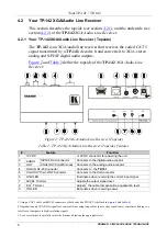
4.2.2 Your TP-142 XGA/Audio Line Receiver (Underside)
define the underside of the
TP-142
XGA/Audio Line
Receiver
:
Figure 3: TP-142 XGA/Audio Line Receiver (Underside)
Table 3: TP-142 XGA/Audio Line Receiver (Underside) Features
#
Feature
Function
10
HS Switch
To set H SYNC to positive polarity, slide the switch to the right
;
to set the H SYNC to negative polarity, slide the switch to the left
11
VS Switch
To set V SYNC to positive polarity, slide the switch to the right
;
to set the V SYNC to negative polarity, slide the switch to the left
12
XGA/VIDEO
Switch
To set for any video signal, such as HDTV, slide the switch to VIDEO;
to set for a computer graphics signal, slide the switch to XGA
5
Connecting the XGA/Audio Line Transmitter/Receiver
You can use the
TP-141
and
TP-142
to configure an XGA / Audio
Line-to-Twisted Pair Transmitter and Receiver system.
To
connect the
TP-141
XGA/Audio Line Transmitter
with the
TP-142
XGA/Audio Line Receiver
, do the following:
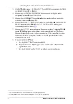
1. On
the
TP-141
, connect the XGA source (for example, the graphics card of a
laptop) to the XGA INPUT 15-pin HD (F) connector.
2. Connect an audio source to the AUDIO IN
3.5mm mini jack, for example,
using a Kramer C-GMA/GMA cable (VGA 15-pin HD (M) +audio jack to
VGA 15-pin HD (M) +audio jack)
.
Alternatively, you can connect an XGA source to the XGA INPUT 15-pin
HD (F) connector, and a separate audio source to the AUDIO IN 3.5mm mini
jack.
1 By default, both switches are set to the left (for a negative V SYNC and H SYNC polarity)
2 Not supplied. The complete list of Kramer cables is on our Web site at
http://www.kramerelectronics.com


