KRAMER: SIMPLE CREATIVE TECHNOLOGY
Connecting the XGA/Audio Line Transmitter/Receiver
8
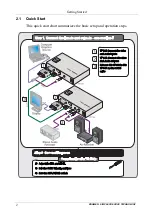
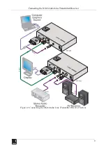
3. On
the
TP-142
, connect the XGA OUT 15-pin HD (F) connector to the XGA
acceptor (for example, a display).
4. Connect the AUDIO OUT S/PDIF
RCA connector to the digital audio
acceptor (for example, an AV receiver).
5. Connect the ANALOG
3.5mm mini jack to the analog
audio acceptor (for
example, a stereo audio recorder).
6. Connect the LINE OUTPUT RJ-45 connector on the
TP-141
to the
LINE IN
RJ-45 connector on the
TP-142
, via CAT 5 (UTP or STP) cabling, (see
7. Connect the 12V DC power adapter to the power socket of either the
TP-141
or the
TP-142
and connect the adapter to the mains electricity. The Power
Connect feature feeds power to the second device. If the second device does
not power on due to a long line, connect a 12V DC power adapter to the
second device as well.
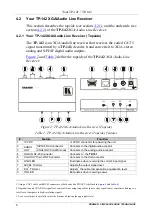
8. If required, On the
TP-142
:
Set the XGA/VIDEO switch to XGA
Adjust
the video output signal level and/or cable compensation
equalization level
Set the H SYNC and V SYNC switches
, on the underside
1 Use a screwdriver to carefully rotate the trimmer, adjusting the appropriate level
2 By default, both switches are set to the left (for negative V SYNC and H SYNC polarity)


