TP-133/TP-134 - Connecting the TP-133/TP-134
7
5
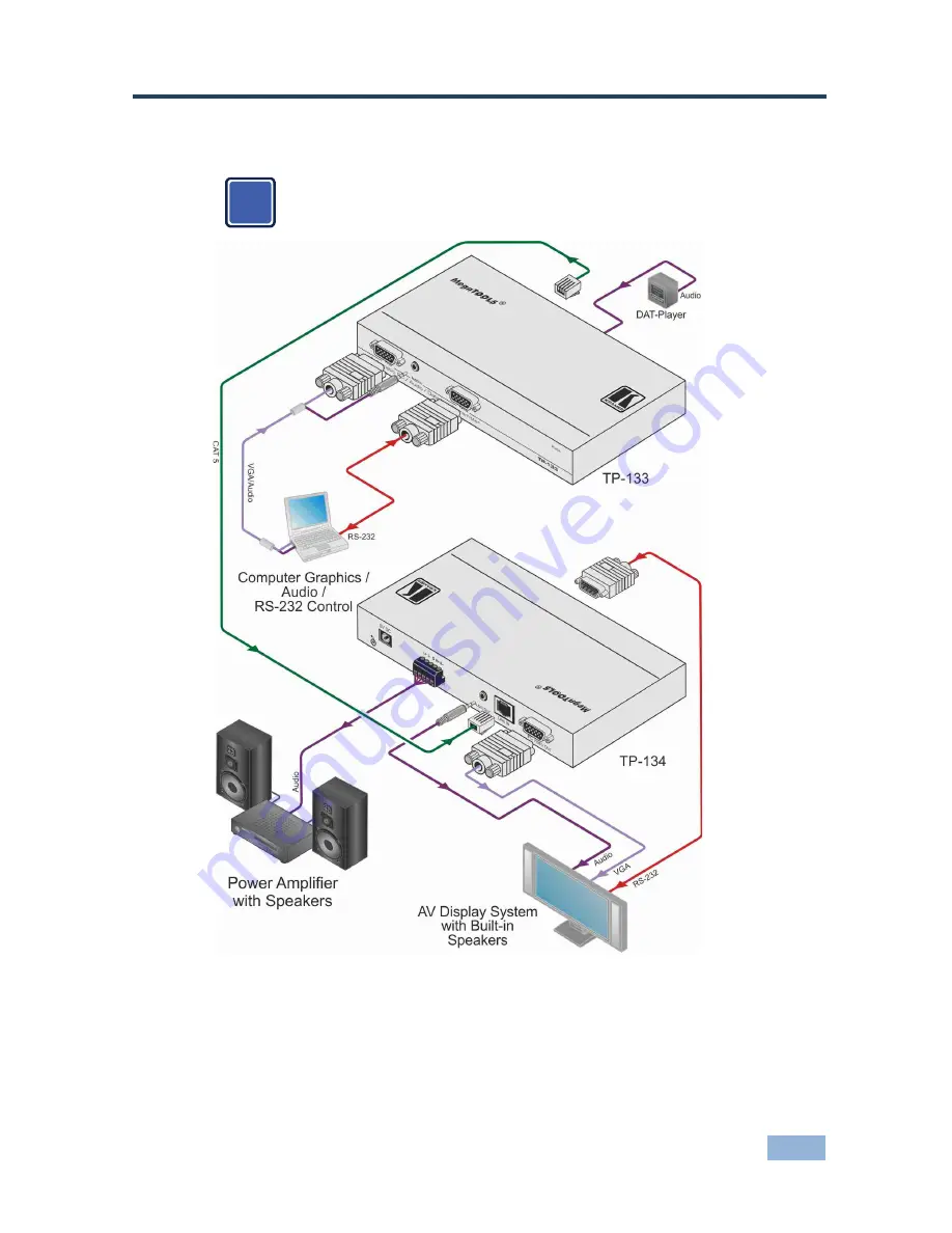
Connecting the TP-133/TP-134
After connecting your
TP-133
and
TP-134
, connect the power
adapters.
Figure 3: Connecting the TP-133/TP-134 PC/Audio/Data Line Transmitter/Receiver System
i
Страница 1: ...KRAMER ELECTRONICS LTD USER MANUAL MODELS TP 133 Automatic PC Audio Data Line Transmitter TP 134 Automatic PC Audio Data Line Receiver P N 2900 300012 Rev 4...
Страница 2: ......
Страница 3: ...and Unbalanced Audio Equipment 9 5 2 Wiring the TP RJ 45 Connectors 9 6 Adjusting RGB and Compensation on the TP 134 10 6 1 Setting the Skew and Equalization Manually 10 6 2 Setting the Skew and Equa...
Страница 4: ...ers GROUP 5 Range Extenders and Repeaters GROUP 6 Specialty AV Products GROUP 7 Scan Converters and Scalers GROUP 8 Cables and Connectors GROUP 9 Room Connectivity GROUP 10 Accessories and Rack Adapte...
Страница 5: ...ing 2 1 Achieving the Best Performance To achieve the best performance Use only good quality connection cables to avoid interference deterioration in signal quality due to poor matching and elevated n...
Страница 6: ...n also be set manually TP 134 Automatic Skew Correction automatically detects and corrects the differential delay in the R G B color components due to the TP cable Can also be set manually TP 134 Full...
Страница 7: ...ic PC Audio Data Line Transmitter The TP 133 is a high performance transmitter that accepts the following signals Computer graphics video Balanced and unbalanced stereo audio RS 232 data The TP 133 en...
Страница 8: ...nced stereo audio acceptor loop output see Section 5 1 8 AUDIO OUT 3 5mm Mini Jack Connect to an unbalanced stereo audio acceptor loop output 9 LINE OUT RJ 45 Connector Connect to the LINE IN RJ 45 co...
Страница 9: ...indicate that the TP link is established Flashes orange to indicate that there is a link problem Flashes green to indicate that the green color is selected 6 POWER RED LED Lights green to indicate tha...
Страница 10: ...onnecting the TP 133 TP 134 7 5 Connecting the TP 133 TP 134 After connecting your TP 133 and TP 134 connect the power adapters Figure 3 Connecting the TP 133 TP 134 PC Audio Data Line Transmitter Rec...
Страница 11: ...erminal block If needed connect a computer monitor and audio amplifier loudspeakers to the looping VGA audio outputs not shown in Figure 3 2 On the TP 134 connect the BAL AUDIO OUT 5 pin terminal bloc...
Страница 12: ...33 TP 134 balanced audio output to an unbalanced acceptor Figure 5 Connecting to an Unbalanced Acceptor 5 2 Wiring the TP RJ 45 Connectors When using STP cable connect solder the cable shield to the R...
Страница 13: ...ually The color and equalization can be set either with the live signal or using the built in pattern generator 6 1 1 Setting the Skew and Equalization Manually Using a Live Signal To set the color an...
Страница 14: ...ation using the built in pattern generator 1 Press and hold the COLOR button for three seconds The RED LED flashes red and the OSD pattern is displayed with a broad red horizontal band across the bott...
Страница 15: ...ashes green together The OSD pattern is displayed with no horizontal band across the bottom to indicate the current setting 8 To change the equalization press the or button to increase or decrease the...
Страница 16: ...1 Balanced stereo audio on a 5 pin terminal block 1 Unbalanced stereo audio on a 3 5mm mini jack Data 1 RS 232 bidirectional on a 9 pin D sub connector CONTROLS Skew Equalization VIDEO RESOLUTION Up t...
Страница 17: ...s of nature ii Product modification orfailure to follow instructions supplied withtheproduct iii Repair orattemptedrepairby anyone not authorized by Kramer iv Any shipment of theproduct claims must be...
Страница 18: ...P N 2900 300012 Rev 4...