Connecting the TBUS-2 Connection Bus
7
5 Connecting the TBUS-2 Connection Bus
This section describes how to connect the
TBUS-2
:
Cut an opening in the table (see section 5.1)
Insert the
TBUS-2
through the cut-out opening (see section 5.2)
Install the required Kramer inserts (see section 5.3)
5.1 Cutting an Opening
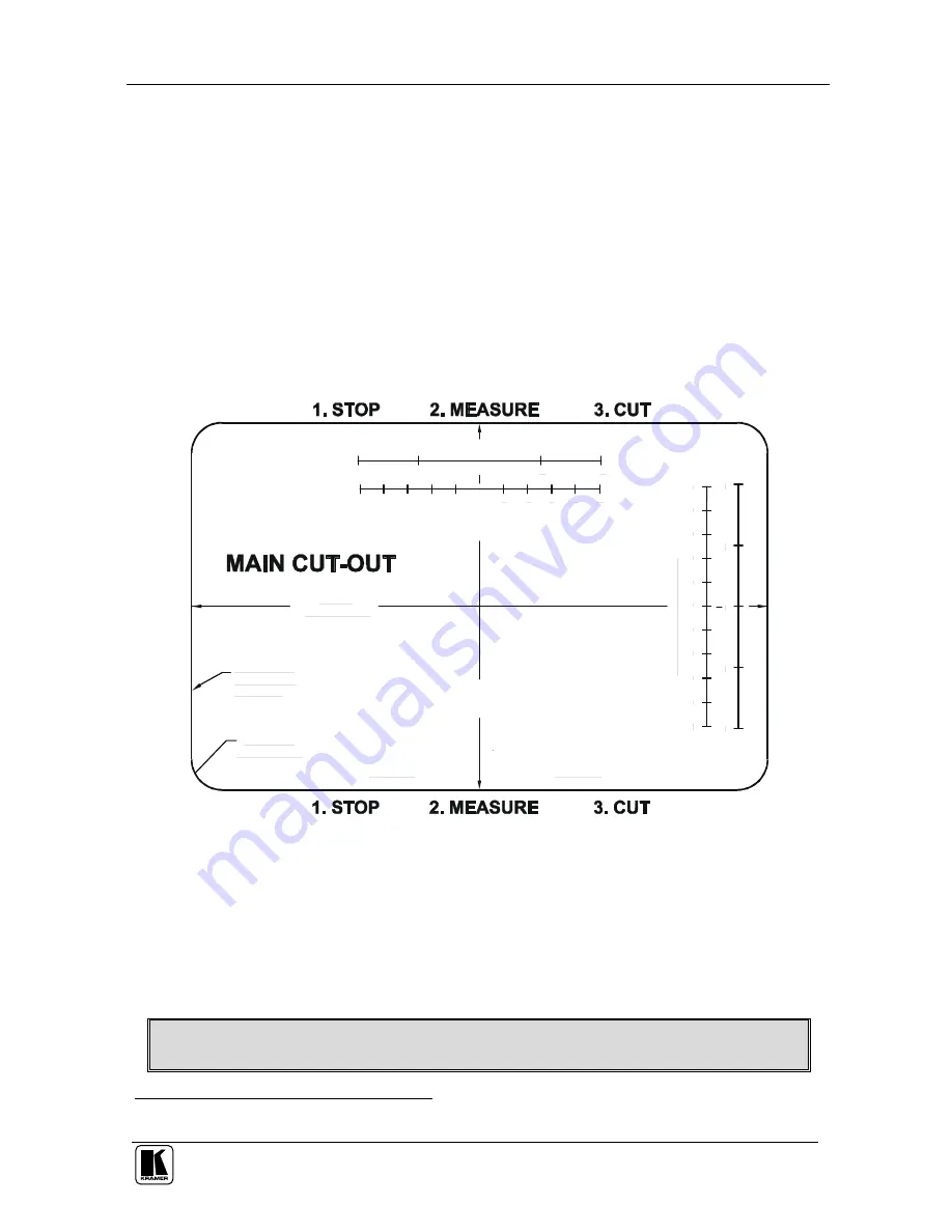
Figure 5 illustrates the cutout template (not to scale) defining the surface you
have to cut out to install your
TBUS-2
.
A template can be downloaded from our Web site
1
6.0
3"
[1
56
.1
3m
m
]
VERIFY ALL DIMENSIONS
TO ENSURE THAT THIS
PRINT IS 1 TO 1 SCALE
MEASURE WITH A RULER
inch.
cm.
CUT TO THE
OUTSIDE OF
THE LINE.
9.470"
[240.54mm]
FRONT
FRONT
4x R.500"
[R12.70mm]
in
ch
.
cm
.
M
E
A
S
U
R
E
W
IT
H
A
R
U
LE
R
.
Figure 5: Cutout Dimensions
The thickness of the table should be 3” or less.
Before cutting the opening, confirm the dimensions and make sure that the
specifications have not changed.
Cut out the wooden surface in which you want to insert the
TBUS-2
. Take
care not to cause damage to the table.
Kramer Electronics is not responsible for any damage caused to the table
1 At http://www.kramerelectronics.com


