Your RC-7LC / RC-7LCE
7
!"#
$%
&
'( )
'* !+
',,)
- '( )
)
% .
/
%
.
.0
. 0
0
('
1
(2 %
) 3 %
#'45+62 %
/ 2
2
(
7 #8 1
#
8
% /0
*(8
9
/ ) %
).%
,! &' 386,!54&
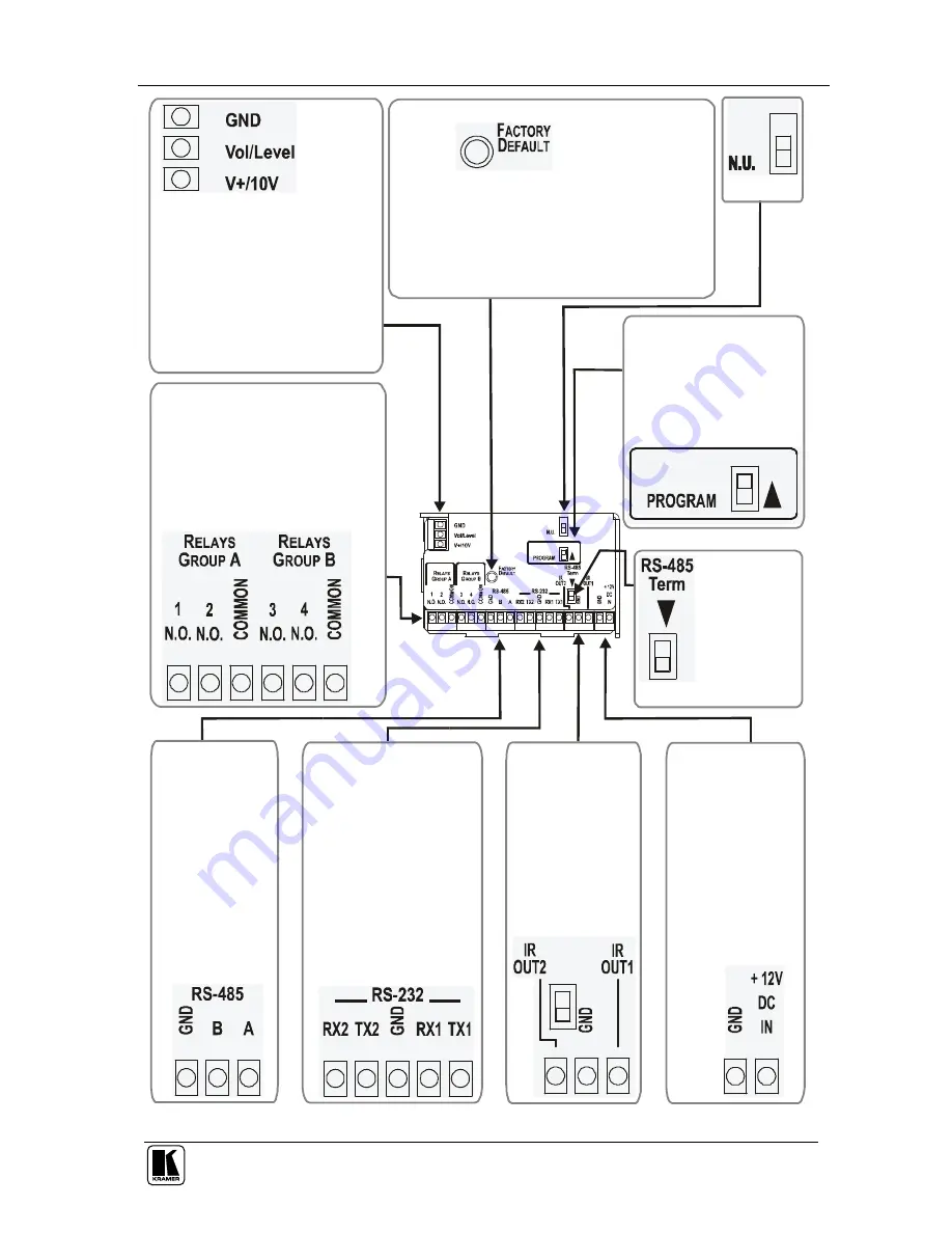
Figure 4: Side Panel of the RC-7LC and RC-7LCE
Страница 1: ...Kramer Electronics Ltd USER MANUAL Models RC 7LC Media Room Controller RC 7LCE Media Room Controller...
Страница 2: ...RS 232 Port 13 6 3 Upgrading Firmware 13 7 Technical Specifications 14 Figures Figure 1 RC 7LC Front Panel 4 Figure 2 RC 7LCE Front Panel 5 Figure 3 Side Panel of the RC 7LC and RC 7LCE Enlarged View...
Страница 3: ...configured 4 Refer to the separate online RC Configuration and Installation guide for details of how to install and configure the Universal Room Media Room Controller 5 1 GROUP 1 Distribution Amplifi...
Страница 4: ...gurable backlit control buttons and three signal source buttons each of which can be programmed3 to carry out up to four macros with 15 commands each A 3 5mm jack on the front panel for configuration...
Страница 5: ...terference from neighboring electrical appliances and position the RC 7LC RC 7LCE away from moisture excessive sunlight and dust Caution No operator serviceable parts inside unit Warning Use only the...
Страница 6: ...3 Faceplate Attachment Holes 2 For attaching the faceplate to the controller 1 4 CONFIG Port 2 Used for Windows based configuration software driver downloads firmware updates and so on 5 SIGNAL SOURC...
Страница 7: ...2 to remotely adjust the volume on the power amplifier 5 CONFIG Port3 Used for Windows based configuration software driver downloads firmware updates and so on 6 IR IN Receiver Accepts IR remote comma...
Страница 8: ...the RC 7LC and RC 7LCE Figure 3 Side Panel of the RC 7LC and RC 7LCE Enlarged View Figure 4 defines the side panel of the RC 7LC and RC 7LCE For an explanation of how to install and configure refer t...
Страница 9: ...Your RC 7LC RC 7LCE 7 0 0 0 1 2 3 4 5 6 2 2 2 1 2 1 7 8 1 8 0 8 9 2 0 386 54 Figure 4 Side Panel of the RC 7LC and RC 7LCE...
Страница 10: ...ront view perspective of a typical RC 7LCE configuration It connects to an amplifier letting you set the volume directly from the RC 7LCE and to the projector via IR or RS 232 Figure 5 RC 7LCE Front P...
Страница 11: ...he dedicated video and audio inputs of the projector and the projector connects to the power amplifier Figure 6 RC 7LCE Rear Perspective Configuration Figure 7 shows the RC 7LCE built into a podium in...
Страница 12: ...KRAMER SIMPLE CREATIVE TECHNOLOGY Using Your Media Room Controller 10 VCR DVD Amplifier Figure 7 Example of a Typical Setup in the Lecture Auditorium...
Страница 13: ...2 Stop the VCR 5 2 Using the Macro Buttons Pressing any button initiates a macro sequence2 during which the button blinks as programmed by the system integrator If during the macro sequence the butto...
Страница 14: ...on the projector and resume the slide show PC Select the PC input on the projector and show the last few slides of the presentation PC Select the VCR input on the projector and show the video film VCR...
Страница 15: ...mer Application 6 2 Connecting the PC to the RS 232 Port Before installing the latest Kramer Ethernet firmware version on the RC LC do the following 1 Connect the special CONFIG cable2 to the CONFIG p...
Страница 16: ...RTS 2 bi directional RS 232 on terminal block connectors 1 RS 485 on a terminal block connector Config jack connector for RS 232 configuration and control OUTPUTS 4 relays on terminal block connectors...
Страница 17: ...tsof nature ii Product modification or failuretofollowinstructions supplied with the product iii Repair or attemptedrepair by anyonenot authorized byKramer iv Anyshipment oftheproduct claims mustbepre...
Страница 18: ...r the latest information on our products and a list of Kramer distributors visit our Web site www kramerelectronics com where updates to this user manual may be found We welcome your questions comment...