background image

6

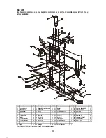
ASSEMBLY INSTRUCTIONS

Use the exploded drawing as your guide to assemble. Lay all parts and assemblies out in front of you 
before beginning. The following procedure is recommended:
•  Attach one base support (02) to left post and lower connecting base (01) using spring washers (05), 
    nuts (06), screw bolts (07) washers (04), then attach another to right post and the lower connecting base.
•  Fix one end of support beam B (09) to the base support (02) and another end to the connecting base 
    (01) using spring washers (05), nuts (06), screw bolts (07) and washers (04).
•  Put another upper crossbeam into position and insert the under plate (29) to the two upper cross 
    beams at the same time, then secure this cross beam to the posts using spring (22) and screw bolts (23).
•  Screw the upper round nut onto the press cylinder (24), insert the press cylinder into the hole in the 
    under plate (29), then screw the under round nut onto the press cylinder and attach the serrated saddle
    to the press cylinder.
•  Insert bed frame pin (34) into the holes in the posts, then insert the joined press bed frame (33) into 
    press frame and onto bed frame pin.
•  Attach the hydraulic pressure pump (11) to the right post using screw bolts (36), spring washers (37). 
    then insert the handle to the handle bracket.
•  Connect the hose fitting (14) to the press cylinder (24) and assemble the press gauge (27) to the 
    pressure gauge connection nut which is on the top of hose fitting (14).
•  Tighten all bolts and screws.

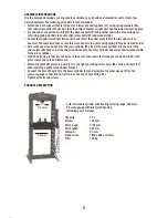
PRODUCT DESCRIPTION

- Lateral movable cylinder with bearing (moving range: 200 mm)
- Pressure gauge with integrated housing
- Including par of V-blocks

Capacity:                     30 t
Stroke:                        150 mm
Work range:                1100 mm
Work width:                 550 mm
Stamp-Ø:                     53 mm
Product size:               1840 x 885 x 700 mm

N.W.:                            165 kg

53 mm

550 mm

Содержание 38122

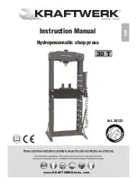
Страница 1: ...www KRAFTWERKtools com EN Art 38122 Instruction Manual Hydropneumatic shop press 30 T...

Страница 2: ...e jewelry and contain long hair Wear ANSI approved impact safety goggles full face impact safety shield and heavy duty work gloves when operating the press Keep proper balance and footing do not over...

Страница 3: ...e pistol When air source is unavaliable use the handle to pump Align workpiece and ram to ensure center loading Turn on air valve pistol or pump the handle to apply load onto workpiece When work is do...

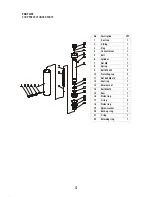
Страница 4: ...0 Back up ring 1 19 Nylon washer 1 18 Piston ring 1 17 O ring 2 16 Piston ring 1 15 Ram 1 14 Bolt M8x10 1 13 Retainer nut 1 12 Seal ring 1 11 Nut bolt M8x10 1 10 Protecting cup 2 9 Bolt M8 x 50 2 8 Sp...

Страница 5: ...re pump Connector O ring Hose fitting Nut M20 Hose fitting Connector Hose fitting Roller shaft Bearing 11 12 13 14 15 16 17 18 19 20 No Description QTY 4 4 1 1 1 1 1 4 1 1 Washer Spring Screw bolt M8x...

Страница 6: ...nd nut onto the press cylinder 24 insert the press cylinder into the hole in the under plate 29 then screw the under round nut onto the press cylinder and attach the serrated saddle to the press cylin...

Страница 7: ...c shop press 30 T KRAFTWERK S rl 25 rue due Stade F 67870 Bischoffsheim Declares under sole responsibility that the product to which this declaration relates is in conformity with the following standa...

Страница 8: ...www KRAFTWERKtools com KRAFTWERK Europe AG Mettlenbachstrasse 23 CH 8617 M nchaltorf Tel 41 44 949 40 50 KRAFTWERK S rl 25 rue du Stade F 67870 Bischoffsheim Tel 33 388 48 64 50 Switzerland France...

Отзывы: