background image

8

Start up

1.  Check if required pressure has been reached within the installation (see section 

"Technical Data"). In order to check it use 

 or 

 button when control panel 

is „on’’.


Flashing A symbol (see section "Failures") indicates too low installation pressure. 

Above description does not apply to open type installations.

2.  Set the pump at constant mode (see section "Advanced settings”).

3.  Switch the boiler on (press 

 button).

4.  Check if the appropriate medium flow rate has been reached (the „H” indicator is 

on with a constant light). The pump should get vented itself after a short working 

time, however, if necessary, vent the pump in the following way:

• 

close the cut-off valve on the outlet,

• 

set the pump on the highest efficiency (see section "Advanced settings”),

• 

let the boiler with the pump on run for 15-30 s.

• 

open the cut off valve.

5.  Switch the boiler off (press and hold 

 button for 3 seconds).

6.  Set the pump at automatic mode (see section "Advanced settings”).

7.  Connect programmed room thermostat.

8.  Switch the boiler on (press 

 button).

9.  Set parameters of heating curve adjusted to the building (heating curve coefficient 

and offset) - see section "Advanced settings".


Reset  of  the  curve  slope  switches  off  weather  compensation  and  starts  boiler's 

operation in accordance with manual adjustments of the installation. 

Содержание EKCO.L2M

Страница 1: ...Electric Central Heating Flow Boiler EKCO LN2M EKCO L2M Assembly and operating manual...

Страница 2: ...lay with the appliance Used product can t be treated as general communal waste Disassembled appliance has to be delivered to the collection point of electrical and electronic equipment for recycling A...

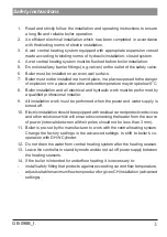
Страница 3: ...all electrical and hydraulic work must be performed by a qualified professional installer 9 All installation work must be performed when the power and water supply is turned off 10 Electric installat...

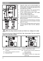
Страница 4: ...5 mm2 to the terminal of control panel RT entry 8 Once you have finished the above procedures you can start the boiler See the Start up section While mounting thermostat make sure there is no voltage...

Страница 5: ...ing installation be larger an extra expansion vessel should be installed on it Temperature of heating medium feed and return Capacity of central heating system Pressure in central heating system C l b...

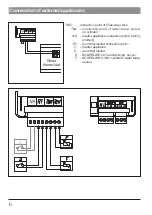
Страница 6: ...int of three way valve Thw connection point of water temp sensor in cylinder NA master appliance connection point factory shorted RT room thermostat connection point C master appliance D room thermost...

Страница 7: ...re is need to extend the wire it is necessary to make it as short as possible If the wire is too long there may occur disturbances and it may not work properly The wires should not run close to mains...

Страница 8: ...tself after a short working time however if necessary vent the pump in the following way close the cut off valve on the outlet set the pump on the highest efficiency see section Advanced settings let...

Страница 9: ...working mode PA automatic PC constant pump s efficiency E E3 0 3 0m E4 0 4 0m E5 0 5 0m E5 0 5 0m E7 0 7 0m E7 5 7 5m pumpe press mode PPn constant pressure difference pressure indicator on variable...

Страница 10: ...its without preceding zeros from the most significant one with 0 5 sec breaks after the display of the least significant digit display is blanked for 2 sec To exit advanced settings and save all chang...

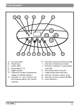
Страница 11: ...g for DHW cylinder G indicator of room thermostat and heating activity for central heating H indicator of pump and flow activity I indicator of data transmission J indicator of weather compensation co...

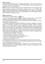
Страница 12: ...ator J is on when weather compensation regulator is active advanced settings Indicator J flashes when there is no possibility to determine installation s temperature due to the lack or failure of outs...

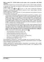
Страница 13: ...Note it works only when weather compensation regulator is switched off advanced settings parameter C 0 or when there is no outside sensor preview and adjustment of water temperature in DHW cylinder i...

Страница 14: ...019 01 sensor is plugged to entry Thw Pressing or buttons when water temperature in cylinder is indicated on the display results in temperature adjustment regulation range 30 80 C indicators D N F on...

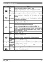
Страница 15: ...perature has been reached boiler co operates with DHW cylinder icon in red temp in CH system is lower than required but the required room temperature has been reached RT entry is open or room thermost...

Страница 16: ...de room thermostat indicates heating on failure of installation that con nects room thermostat check connecting installation failure of electronic module contact authorised service K indicator flicker...

Страница 17: ...ower kW 4 6 8 4 6 8 12 Rated voltage 230V 400V 3N Rated current A 17 4 26 0 34 8 3x5 7 3x8 7 3x11 7 3x17 3 Min power supply cable cross section mm2 3x2 5 3x4 3x6 5x1 5 5x2 5 Max power supply cable cro...

Страница 18: ...18 Connection of three way valve diagrams AZV 642 PUMP TWV AZV642 valve connection diagram Brown Blue Black...

Страница 19: ...19 GB 096B_f PUMP TWV Honeywell valve connection diagram Brown Blue Black...

Страница 20: ...KOSPEL S A 75 136 Koszalin ul Olchowa 1 tel 48 94 31 70 565 serwis kospel pl www kospel pl...

Отзывы: