


3. Power the unit and connect to network
3.1 Connect the PWR1 / PWR2, and the unit will power on. PWR1 / PWR2 LED will turn
Red to show the unit is booting up. When the unit is ready, the LED turns Green.
Device Management
JetNet Industrial Managed Switch provides both in-band and out-band configuration
methods. You can configure the switch via the RS232 console with the attached console
cable or you can remotely manage the switch via network. You can choose Telnet/SSH, Web/
HTTPS management.
3.2 Connect the 10/100M Ethernet Port: Connect the network nodes to the JetNet switch
with 2/4-pair CAT5 UTP cable. The 10/100M interfaces support auto MDI/MDIX.
3.3 Connect the Gigabit TX of combo ports: Connect the network node to the JetNet switch
with 4-pair CAT5 UTP cable. The Gigabit TX interfaces support auto MDI/MDIX as well.
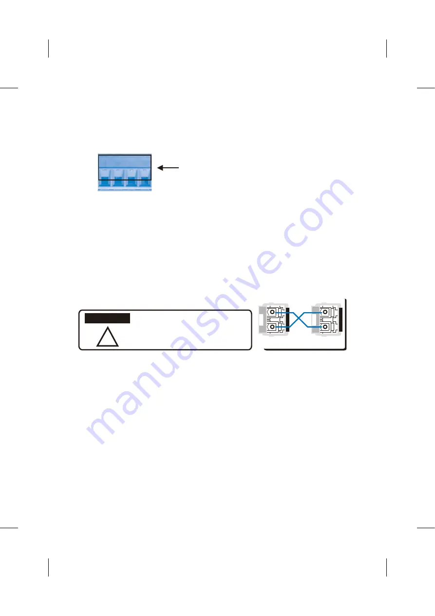
3.4 Connect the SFP transceiver: Plug in SFP fiber transceiver. We recommend using
Korenix certificated SFP mini GBIC transceiver. Cross-connect the transmit channel at
each end to the receive channel at the opposite end as illustrated in the figure below.
V+
V-
V+
V-
Power1
Power2
Accept 12~24AWG wire. The switch
provides polarity reverse protection
Ȋ
This is a Class 1 Laser/LED product.
Don’t stare at the Laser/LED Beam.
TX
RX
A
B
TX
RX
ATTENTION
3.5 If you need to connect the Relay Output, please refer to the wiring method introduced
in the manual.
1. Preparation for the console management: Attach the RS-232 DB9 connector to your PC’s
COM port. Connect the RJ-45 connector to the console port of the JetNet Industrial Managed
Switch.
1.1 Go to Start -> Program -> Accessories -> Communication -> Hyper Terminal


