background image

5

Operating the cable tester

Testing cables:

1.  Plug the connectors of the cable into the corresponding jacks on either side of the cable tester.

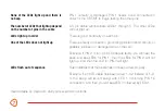
2.  Set the Power Switch on the sender to the ON position. The power LED will glow red. The first three 

LEDs will light in sequence indicating that batteries are installed in both battery compartments. 
 
Note: The flashing LEDs at this point do not indicate cable continuity. They only indicate that 
batteries are installed into both sender and receiver.

3.  Switch the Cable Test/Tone Test selector on the receiver to the Cable Test position. The power 

LED will glow green.

4.  If both ends of the cable are properly connected, the pin continuity LEDs will begin to flash and a 

beep will repeat to confirm the continuity of PIN 1. 
 
Important: If the LEDs and beep do not start immediately once the receiver has been turned 
on, it indicates that PIN 1 of the cable is faulty.  PIN 1 needs to be connected in order for the 
CBT-MF to begin working.

Содержание CBT-MF

Страница 1: ...Multi Function Dual Chassis CABLE TESTER User Manual CBT MF...

Страница 2: ...have been run through walls or ceilings as well as cables that have been put into audio or home theater installations LED indicators and a beep verify that each pin on the cable is properly connected...

Страница 3: ...periods of non use Do not attempt to disassemble or repair the equipment doing so will void the warranty and Kopul will not be responsible for any damage Clean the unit with a soft dry cloth Use only...

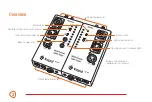
Страница 4: ...acks Battery compartments underside not shown Pin indicator and continuity LEDs Cable testing jacks LED speed selector Power LEDs Cable test Tone test power selector Tone test volume selector Power sw...

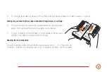
Страница 5: ...ttery compartment cover by pressing the locking tab and removing the cover 2 Insert the terminals of the snap connector onto the battery 3 Place the battery into the battery compartment making sure to...

Страница 6: ...indicate cable continuity They only indicate that batteries are installed into both sender and receiver 3 Switch the Cable Test Tone Test selector on the receiver to the Cable Test position The power...

Страница 7: ...nd receiver can be separated by sliding them apart Connect each side to the cable to be tested 7 The pin indicator LEDs will flash on both sides to show each operator the status of each pin s continui...

Страница 8: ...LEDs 1 through 5 The other LEDs will not light up There is good continuity on each pin There is a faulty connection grounding problem short circuit or possibly a broken or damaged wire on that pin Ex...

Страница 9: ...nd of the cable 3 A lit LED accompanied by a beep indicates good connectivity and continuity Using test tones 1 Switch the Cable Test Tone Test selector on the receiver to the Tone Test position The p...

Страница 10: ...eeve 3 Ring shorted with sleeve Speakon 1 1 2 1 3 2 4 2 Phono 1 screen 2 hot Pin 1 Pin 2 Pin 3 Pin 1 Pin 3 Pin 2 Pin 1 Pin 3 shorted with sleeve 1 Sleeve 3 Ring 2 Tip 3 Ring Pin 1 Pin 3 Pin 2 Pin 1 Pi...

Страница 11: ...Test tone amplitude Power 1 25 6 5 6 3 2 16 5 15 2 cm Each chassis W 3 25 8 2 cm 1 4 lb 0 6 kg Speakon 4 pin XLR M F 3 pin XLR M F 5 pin RCA Phono DIN 3 pin 5 pin TRS TRS 3 5 mm RJ45 RJ11 BNC Banana...

Страница 12: ...sed by misuse neglect accident alteration abuse improper installation or maintenance EXCEPT AS PROVIDED HEREIN THE WARRANTY PROVIDER MAKES NEITHER ANY EXPRESS WARRANTIES NOR ANY IMPLIED WARRANTIES INC...

Отзывы: