Kontron SMARC-sAMX8 - Rev. 1.2
www.kontron.com
// 19
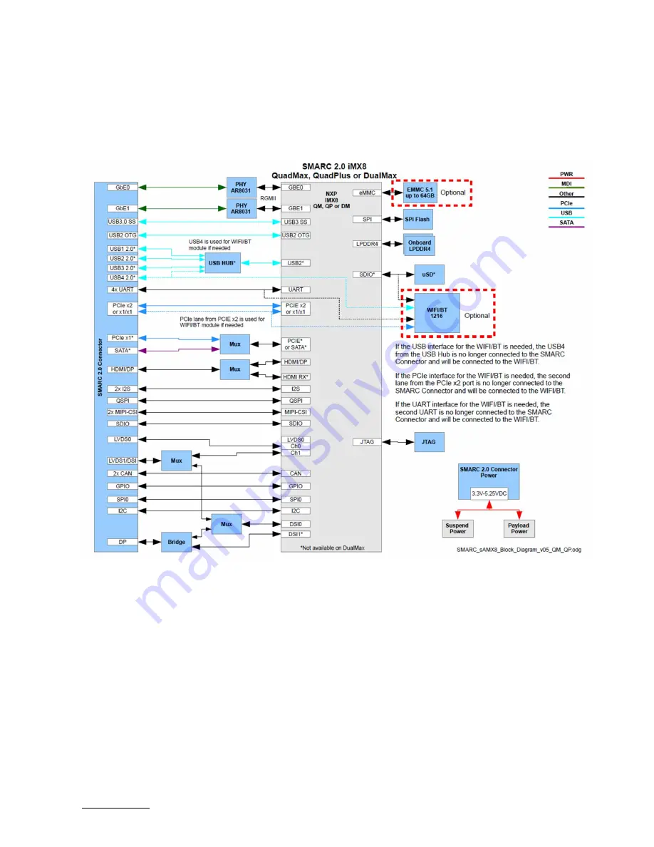
3.3. Functional Block Diagram
The block diagram shows all available interfaces on the sAMX8 module.
Figure 2: Block Diagram
Страница 1: ...USER GUIDE www kontron com Kontron SMARC sAMX8 User Guides Doc Rev 1 2 Preliminary Doc ID To be Determined...
Страница 2: ...Kontron SMARC sAMX8 Rev 1 2 www kontron com 2 This page has been intentionally left blank...
Страница 3: ...ill be suitable for the specified use without further testing or modification Kontron expressly informs the user that this user guide only contains a general description of processes and instructions...
Страница 4: ...quate design and operating safeguards You are solely responsible for compliance with all legal regulatory safety and security related requirements concerning your products You are responsible to ensur...
Страница 5: ...guide or visit our website CONTACT US Customer Support Find Kontron contacts by visiting http www kontron com support Customer Service As a trusted technology innovator and global solutions provider...
Страница 6: ...ribed by the law may endanger your life health and or result in damage to your material ESD Sensitive Device This symbol and title inform that the electronic boards and their components are sensitive...
Страница 7: ...efore performing any work on this product Earth ground connection to vehicle s chassis or a central grounding point shall remain connected The earth ground cable shall be the last cable to be disconne...
Страница 8: ...duct then re pack it in the same manner as it was delivered Special care is necessary when handling or unpacking the product See Special Handling and Unpacking Instruction Quality and Environmental Ma...
Страница 9: ...19 4 Board and Connectors 21 4 1 1 Connectors 21 4 2 Mainboard view and I O locations 21 4 3 Bottom Side 22 4 4 Mechanical Drawings 23 4 5 Thermal Considerations 24 5 Pin Definitions 25 5 1 Processor...
Страница 10: ...loader File System Support 54 7 9 Bootloader Network Support 54 7 10 Bootloader Boot Source Support 55 7 11 Bootloader Boot Counter 55 7 12 Bootloader Update 56 8 Linux OS 57 8 1 Software Images 57 8...
Страница 11: ...RT connections between CPU and SMARC 2 0 connector 46 Table 12 Bootloader Command Extensions 50 Table 13 Standard Environment Variables 52 Table 14 Bootloader Environment Extensions 53 Table 15 Enviro...
Страница 12: ...rrent SMARC product family by adding features and performance Specifically the iMX8 SMARC module is a performance upgrade from the iMX8X product in that it delivers higher CPU and graphics processing...
Страница 13: ...racterized by the extremely flat form factor The SMARC or MXM 3 0 connector comes with 314 pins and a construction height of just 4 3 millimeters The connector is also available in a shock and vibrati...
Страница 14: ...and 1x USB3 0 SS shared with one USB2 0 Support for Audio output and common features SPI I2C SMB etc Optional eMMC flash onboard Full industrial grade temp range E2 40 C up to 85 C for standard SKUs c...
Страница 15: ...USB 3 0 SS If WIFI BT module is installed USB5 is not accessible PCIe Interface 4 3x 3x PCIe 3 0 lane 2 root ports 1 PCIe C is shared with SATA port SATA Interface 1 1x 1x SATA SATA is shared with PCI...
Страница 16: ...bit LVDS RGB True Color Resolution up to 1920x1080 60Hz Single Dual Channel Display DP HDMI HDMI DisplayPort from SoC PCIe SATA 3x PCIe lanes 1 SATA Shared with 1x PCIe Onboard Controllers Ethernet Co...
Страница 17: ...s for general purpose devices SER 4x serial ports with full function according to SMARC 2 0 GPIO 12x General Purpose Inputs Outputs GPIO Other Connectivity 2x CAN Power Consumption Maximum Power consu...
Страница 18: ...to IEC 60068 2 78 Electromagnetic Compatibility EMC According to EN55022 Class B EN61000 6 2 and EN61000 6 4 CE EN 62368 1 2014 Safety for audio video and information technology equipment UL Component...
Страница 19: ...Kontron SMARC sAMX8 Rev 1 2 www kontron com 19 3 3 Functional Block Diagram The block diagram shows all available interfaces on the sAMX8 module Figure 2 Block Diagram...
Страница 20: ...Kontron SMARC sAMX8 Rev 1 2 www kontron com 20...
Страница 21: ...sAMX8X Connector Function Remark SMARC Central Interface Mating connector SMARC 2 0 MXM3 4 2 Mainboard view and I O locations Figure 3 Top View 1 LPDDR4 memory 2 Freescale Processor i MX8 3 WIFI Blue...
Страница 22: ...Kontron SMARC sAMX8 Rev 1 2 www kontron com 22 4 3 Bottom Side Figure 4 Bottom Side from SMARC sAMX8 7 MIPI DSI to eDP DP controller 8 SPI Flash 9 USB Hub 10 eMMC 11 PMICs 7 8 9 10 11...
Страница 23: ...Kontron SMARC sAMX8 Rev 1 2 www kontron com 23 4 4 Mechanical Drawings Figure 5 Dimensions of SMARC sAMX8 Figure 6 Thickness from side view...
Страница 24: ...Considerations The Cooling concept is based on a standard cooler for SMARC modules with mounting holes for iMX8 module Figure 7 Heatspreader Top View with screw holes Figure 8 Heatspreader Bottom View...
Страница 25: ...in 0 75 mm pitch available Table 6 Processor Support Name Core RAM Cache Tj QuadPlus A 53 4x 1 26 GHz A 72 1x 1 6GHz M4F 2x 266MHz 2x GPU GC7000Lite XSVX LPDDR4 no ECC 1MB with ECC 40 C to 125 C Quad...
Страница 26: ...class 5 erase class 6 write protection class 7 lock card HS200 HS400 modes DDR modes up to 52 MHz clock speed ECC and block management Boot operation High speed boot Sleep mode Permanent and power on...
Страница 27: ...VDS Channel1 Note DSI0 from SoC is connected to DSI1 on SMARC connector DSI1 LVDS0 Channel1 Standard SMARC 2 0 module pinout Allow to choose between the DSI0 from the SoC or the LVDS0 Channel1 Do note...
Страница 28: ...25M P7 CSI1_RX0 In LVDS D PHY iMX8 P8 CSI1_RX0 In LVDS D PHY iMX8 P9 GND GND P10 CSI1_RX1 In LVDS D PHY iMX8 P11 CSI1_RX1 In LVDS D PHY iMX8 P12 GND GND P13 CSI1_RX2 In LVDS D PHY iMX8 P14 CSI1_RX2 In...
Страница 29: ...OS 1 8V iMX8 P55 ESPI_CS1 Out Serial 33R CMOS 1 8V iMX8 P56 ESPI_CK Out Serial 33R CMOS 1 8V iMX8 P57 ESPI_IO_1 Bi Dir Serial 33R CMOS 1 8V iMX8 P58 ESPI_IO_0 Bi Dir Serial 33R CMOS 1 8V iMX8 P59 GND...
Страница 30: ...Out TMDS iMX8 P103 GND GND P104 HDMI_HPD DP1_HPD In PD 100k CMOS 1 8V iMX8 P105 HDMI_CTRL_CK DP1_AUX Bi Dir PU 2k2 CMOS 1 8V iMX8 V_1V8 P106 HDMI_CTRL_DAT DP1_AUX Bi Dir PU 2k2 CMOS 1 8V iMX8 V_1V8 P1...
Страница 31: ...P131 SER0_RTS Out CMOS 1 8V iMX8 P132 SER0_CTS In CMOS 1 8V iMX8 P133 GND GND P134 SER1_TX Out CMOS 1 8V iMX8 P135 SER1_RX In CMOS 1 8V iMX8 P136 SER2_TX Out CMOS 1 8V iMX8 P137 SER2_RX In CMOS 1 8V i...
Страница 32: ...0 Bi Dir GBE MDI AR8031 S18 GBE1_MDI0 Bi Dir GBE MDI AR8031 S19 GBE1_LINK100 Out OD CMOS 3 3V AR8031 S20 GBE1_MDI1 Bi Dir GBE MDI AR8031 S21 GBE1_MDI1 Bi Dir GBE MDI AR8031 S22 GBE1_LINK1000 Out OD CM...
Страница 33: ...61 GND GND S62 USB3_SSTX Out Serial 100n USB SS iMX8 S63 USB3_SSTX Out Serial 100n USB SS iMX8 S64 GND GND S65 USB3_SSRX In USB SS iMX8 S66 USB3_SSRX In USB SS iMX8 S67 GND GND S68 USB3 Bi Dir USB iMX...
Страница 34: ...LCD1_BKLT_EN Out CMOS 1 8V iMX8 S108 LVDS1_CK DSI1_CLK Out Serial 0R LVDS LCD iMX8 S109 LVDS1_CK DSI1_CLK Out Serial 0R LVDS LCD iMX8 S110 GND GND S111 LVDS1_0 DSI1_D0 Out Serial 0R LVDS LCD iMX8 S11...
Страница 35: ...1 8V iMX8 S142 RSVD NC S143 GND GND S144 EDP0_HPD In NC CMOS 1 8V S145 WDT_TIME_OUT Out CMOS 1 8V Buffers S146 PCIE_WAKE In PU 10k CMOS 3 3V iMX8 V_3V3 S147 VDD_RTC Diode and Measurement circuit PWR R...
Страница 36: ...6 CSI1_RX3 In LVDS D PHY iMX8 P17 CSI1_RX3 In LVDS D PHY iMX8 P18 GND GND P19 GBE0_MDI3 Bi Dir GBE MDI AR8031 P20 GBE0_MDI3 Bi Dir GBE MDI AR8031 P21 GBE0_LINK100 Out OD CMOS 3 3V AR8031 P22 GBE0_LINK...
Страница 37: ...r USB iMX8 P61 USB0 Bi Dir USB iMX8 P62 USB0_EN_OC Bi Dir OD PU 10k CMOS 3 3V iMX8 V_3V3 P63 USB0_VBUS_DET In PD 4k7 USB VBUS 5V iMX8 P64 USB0_OTG_ID In CMOS 3 3V iMX8 P65 USB1 Bi Dir USB USB4604 P66...
Страница 38: ...GPIO2 CAM0_RST Bi Dir PU 100k CMOS 1 8V iMX8 V_1V8 P111 GPIO3 CAM1_RST Bi Dir PU 100k CMOS 1 8V iMX8 V_1V8 P112 GPIO4 HDA_RST Bi Dir PU 100k CMOS 1 8V iMX8 V_1V8 P113 GPIO5 PWM_OUT Bi Dir PU 100k CMO...
Страница 39: ...iMX8 P140 SER3_TX Out CMOS 1 8V iMX8 P141 SER3_RX In CMOS 1 8V iMX8 P142 GND GND P143 CAN0_TX Out CMOS 1 8V iMX8 P144 CAN0_RX In CMOS 1 8V iMX8 P145 CAN1_TX Out CMOS 1 8V iMX8 P146 CAN1_RX In CMOS 1...
Страница 40: ...DI0 Bi Dir GBE MDI AR8031 S18 GBE1_MDI0 Bi Dir GBE MDI AR8031 S19 GBE1_LINK100 Out OD CMOS 3 3V AR8031 S20 GBE1_MDI1 Bi Dir GBE MDI AR8031 S21 GBE1_MDI1 Bi Dir GBE MDI AR8031 S22 GBE1_LINK1000 Out OD...
Страница 41: ...61 GND GND S62 USB3_SSTX Out Serial 100n USB SS iMX8 S63 USB3_SSTX Out Serial 100n USB SS iMX8 S64 GND GND S65 USB3_SSRX In USB SS iMX8 S66 USB3_SSRX In USB SS iMX8 S67 GND GND S68 USB3 Bi Dir USB iMX...
Страница 42: ...SN65DSI86 S107 LCD1_BKLT_EN Out CMOS 1 8V iMX8 S108 SPI3_SCK DSI1_CLK Out Serial 33R LVDS LCD iMX8 S109 SPI3_CS0 DSI1_CLK Out Serial 33R LVDS LCD iMX8 S110 GND GND S111 SPI3_SDO DSI1_D0 Out Serial 33R...
Страница 43: ...CMOS 1 8V iMX8 S142 RSVD NC S143 GND GND S144 EDP0_HPD In NC CMOS 1 8V S145 WDT_TIME_OUT Out CMOS 1 8V Buffers S146 PCIE_WAKE In PU 10k CMOS 3 3V iMX8 V_3V3 S147 VDD_RTC Diode and Measurement circuit...
Страница 44: ...sAMX8 BOOT_SEL2 BOOT_SEL1 BOOT_SEL0 0 GND GND GND Carrier SATA No 1 GND GND Float Carrier SD Card From U Boot 2 GND Float GND Carrier eSPI CS0 No 3 GND Float Float Carrier SPI CS0 No 4 Float GND GND...
Страница 45: ...C 2 08V 1 71 V RV 8803 is powered through Schottky diode BAS70 from V_VDD_RTC pin S147 of SMARC connector 6 3 UART Interfaces Use following UART interfaces with control signals of i MX8 Table 10 Mappi...
Страница 46: ...R2_TX UART1_RX SER2_RX UART1_RTS_B SER2_RTS UART1_CTS_B SER2_CTS UART2 UART0_RTS_B UART2 RX SER0_RTS UART0_CTS_B UART2 TX SER0_CTS UART3 M41_GPIO0_00 UART3 RX GPIO2 CAM0_RST M41_GPIO0_01 UART3 TX GPIO...
Страница 47: ...s will turn off power to the module Power Button Override 6 4 3 Power Bad Signal VIN_POWER_BAD The SMARC sAMX8 provides an external input for a Carrier Board Power Bad signal Pin S150 The implementati...
Страница 48: ...nnected with the edge connector SER0 port of the module On Kontron SMARC 2 0 carrier this port is named SER_0 Start a suitable terminal program on your host and attach it to the port connected with th...
Страница 49: ...ron com 49 SCSI Net Warning ethernet 5b040000 using MAC address from ROM eth0 ethernet 5b040000 PRIME Warning ethernet 5b050000 using MAC address from ROM eth1 ethernet 5b050000 Fastboot Normal Normal...
Страница 50: ...i view DULG UBoot On the SMARC_sAMX8 bootloader the powerful hush shell is enabled which is similar to Bourne shell and provides features similar to a linux shell Control structures if then else fi et...
Страница 51: ...is converted into hexadecimal values and compared against the calculated one Syntax help md5sum md5sum compute MD5 message digest Usage md5sum address count sum compute MD5 message digest save to sum...
Страница 52: ...edit name edit environment variable env exists name tests for existence of variable env print a name print environment env run var run commands in an environment variable env save save environment en...
Страница 53: ...omatically each time U Boot starts They will override different settings possibly stored in persistent environment 7 7 Bootloader Mass Storage Support U Boot provides support to read and write from ma...
Страница 54: ...for both onboard Ethernet interfaces The current interface can be selected by setting ethact environment variable to either FEC0 or FEC1 Board specific MAC addresses are read from EEPROM during start...
Страница 55: ...t_sel environment variable to select the source where the dedicated OS image can be loaded As an example the bootloader environment of the SMARC_sAMX8 implements some small scripts that will load a li...
Страница 56: ...PI sf probe 0 sf erase 0 200000 The SPI image should be loaded with 0 offset into FlexSPI Load the bootloader image to memory address 0x88000000 from a usb key usb start usb dev 0 fatload usb 0 1 8800...
Страница 57: ...project build generates an integrated SD card image sdcard that can be flashed directly onto the SD card The sdcard image contains all images U boot kernel and RootFS properly configured for an SD ca...
Страница 58: ...rom eMMC 8 3 1 Preparing eMMC Using UUU Tool Download from https github com NXPmicro mfgtools releases Follow these instructions to use the Universal Update Utility UUU 1 Connect a USB cable from a co...
Страница 59: ...TFTP boot 8 4 1 Preparing TFTP and NFS setup This section describes the steps to configure the Trivial File Transfer Protocol TFTP server and Network File System NFS server on the host system U Boot...
Страница 60: ...tc exports to be configured correctly to access NFS filesystem directory to specific hosts vi etc exports Then edit below line into the opened file NFS DIRECTORY BOARD IP rw sync no_root_squash no_sub...
Страница 61: ...be used Configure the serial line using 115200 baud 8 data bits 1 stop bit no parity Once the kernel starts the below messages shall appear on the console Starting kernel 0 000000 Booting Linux on ph...
Страница 62: ...P directory as explained in section 9 4 1 section cp m4_0_image bin samx8 boot kontron_smx8qm tftp cp m4_1_image bin samx8 boot kontron_smx8qm tftp On the sAMX8 target board enter the below commands t...
Страница 63: ...etected This can be achieved through a watchdog service or daemon which opens the dev watchdog and refreshes it periodically to keep the kernel from resetting When the daemon stops refreshing the watc...
Страница 64: ...sample user space application is located in the file system path given below The sample application uses the IOCTL calls to set the Watchdog timeout using the WDIOC_SETTIMEOUT parameter Note It is im...
Страница 65: ...Dual Stage Test Note It is important to make sure the watchdog service is inactive before trying to perform watchdog reset test Please refer to the precedent section Watchdog Reset test and follow ei...
Страница 66: ...62 478523 ffff000008a07044 imx8_wdt_notify 0x2c 0x38 262 484014 ffff0000080ef720 notifier_call_chain 0x50 0x90 262 489850 ffff0000080f0010 blocking_notifier_call_chain 0x48 0x70 262 496472 ffff0000085...
Страница 67: ...number can be found on the Type Label located on the product s rear side Be ready to explain the nature of your problem to the service technician 9 1 Warranty Due to their limited service life parts...
Страница 68: ...r Kontron Europe GmbH and fill out the form Take care to include a short detailed description of the observed problem or failure and to include the product identification Information Name of product P...
Страница 69: ...y IOL IPMI Over LAN IOT Internet of Things IPMI Intelligent Platform Management Interface KCS Keyboard Controller Style KVM Keyboard Video Mouse MEI Management Engine Interface NCSI Network Communicat...
Страница 70: ...Kontron SMARC sAMX8 Rev 1 2 www kontron com 70 0 32 Front Panel chapter with colors Safety note added 2019 10 21...
Страница 71: ...ts and tailor made solutions based on highly reliable state of the art embedded technologies Kontron provides secure and innovative applications for a variety of industries As a result customers benef...
Страница 72: ...Kontron SMARC sAMX8 Rev 1 2 www kontron com 72...