


COMe-mAL10 – User Guide, Rev. 1.3
www.kontron.com
// 51
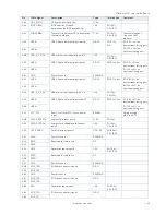
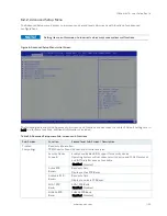
Pin
COMe Signal
Description
Type
Termination
Comment
B99
DDI0CTRLDATA_AUX-
DDIO auxiliary data control
signal
PD 100 k
Ω
,
3,3V (S0)
B100
GND
Power Ground
PWR GND
B101
FAN_PWMOUT
Fan speed control by PWM
Output
O-3.3
20 V protection circuit
implemented on
module, PD on carrier
board needed for
proper operation.
Default frequency of
PWM signal is 25kHz.
B102
FAN_TACHIN
Fan tachometer input for fan
with a two-pulse output
I-3.3
PU 47 k
Ω
,
3.3 V (S0)
20 V protection circuit
implemented on
module
B103
SLEEP#
Sleep button signal used by
ACPI operating system to bring
system to sleep state or wake it
up again
I-3.3
PU 47 k
Ω
,
3.3 V (S5)
B104
VCC_12V
Main input voltage (4.75 V-20 V)
PWR
4.75 V to
20 V
B105
VCC_12V
B106
VCC_12V
B107
VCC_12V
B108
VCC_12V
B109
VCC_12V
B110
GND
Power Ground
PWR GND
+ and -
Differential pair differentiator


