USER GUIDE
COMe-mAL10
Doc. User Guide, Rev. 1.3
Doc. ID: 1061-1952
Страница 1: ...USER GUIDE COMe mAL10 Doc User Guide Rev 1 3 Doc ID 1061 1952...
Страница 2: ...COMe mAL10 User Guide Rev 1 3 www kontron com 2 This page has been intentionally left blank...
Страница 3: ...be suitable for the specified use without further testing or modification Kontron expressly informs the user that this user guide only contains a general description of processes and instructions whi...
Страница 4: ...s is entirely at your risk To minimize the risks associated with your products and applications you should provide adequate design and operating safeguards You are solely responsible for compliance wi...
Страница 5: ...s and conditions Kontron sells products worldwide and declares regional General Terms Conditions of Sale and Purchase Order Terms Conditions Visit http www kontron com terms and conditions For contact...
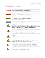
Страница 6: ...ed and or prescribed by the law may endanger your life health and or result in damage to your material ESD Sensitive Device This symbol and title inform that the electronic boards and their components...
Страница 7: ...before performing any work on this product Earth ground connection to vehicle s chassis or a central grounding point shall remain connected The earth ground cable shall be the last cable to be discon...
Страница 8: ...oduct then re pack it in the same manner as it was delivered Special care is necessary when handling or unpacking the product See Special Handling and Unpacking Instruction Quality and Environmental M...
Страница 9: ...hen re pack the product in the same manner as it was delivered Special care is necessary when handling or unpacking the product See Special Handling and Unpacking Instruction Environmental Protection...
Страница 10: ...6 LVDS 20 2 3 7 Audio 20 2 3 8 PCI Express PCIE Lanes 0 3 20 2 3 9 USB 21 2 3 10 SATA 21 2 3 11 Ethernet 22 2 3 12 COMe High speed Serial Interfaces Overview 22 2 3 13 Storage Features 23 2 3 14 BIOS...
Страница 11: ...em Resources 38 4 1 Interrupt Request IRQ Lines 38 4 2 Memory Area 38 4 3 I O Address Map 39 4 4 Peripheral Component Interconnect PCI Devices 40 4 5 I2C Bus 40 4 6 System Management SM Bus 41 5 COMe...
Страница 12: ...in Assignment A1 A110 44 Table 26 Connector X1A Row B Pin Assignment B1 B110 48 Table 27 Navigation Hot Keys Available in the Legend Bar 52 Table 28 Main Setup Menu Sub screens and Functions 54 Table...
Страница 13: ...et 2x USB 3 0 incl USB 2 0 6x USB 2 0 2x SATA Gen 3 Support for both commercial and Industrial temperature grade environments 1 2 Product Naming Clarification COM Express defines a Computer on Module...
Страница 14: ...integrated computer All Kontron COM Express modules are very compact and feature a standardized form factor and a standardized connector layout that carry a specified set of signals Each COM is based...
Страница 15: ...ntel Celeron N3350 4GB DDR3L memory down commercial temperature 2 1 2 Industrial Temperature Grade Modules E2 40 C to 85 C Table 3 Product Number for Industrial Grade Modules 40 C to 85 C operating Pr...
Страница 16: ...through Slimline heatspreader 6 5mm for COMe mAL10 commercial and industrial grade through holes Table 5 COMe Type 10 Accessories Part Number COMe Carrier Description 34105 0000 00 x COM Express Refe...
Страница 17: ...ide Rev 1 3 www kontron com 17 2 3 Functional Specifications 2 3 1 Block Diagram COMe mAL10 The following figure displays the system block diagram applicable to all COMe mAL10 modules Figure 1 Block D...
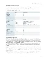
Страница 18: ...7 Specification of the COMe mAL10 Processor Variants Intel Atom Atom Atom Pentium Celeron x7 E3950 x5 E3940 x5 E3930 N4200 N3350 of Cores 4 4 2 4 2 of Threads 4 4 2 4 2 Processor Base Frequency 1 6 GH...
Страница 19: ...ific system memory features Memory Down 4 GB and 8 GB DDR3L Non ECC for commercial temperature grade ECC for industrial temperature grade Peak Bandwidth 29 86 GB s for commercial temperature grade 25...
Страница 20: ...1280 PWM Backlight Control Supported Supported Panel Data JILI EDID VESA DisplayID 2 3 7 Audio The Intel HDA link allows for a maximum of one codec to be connected 2 3 8 PCI Express PCIE Lanes 0 3 Fou...
Страница 21: ...in the following table COMe Port SoC High Speed I O Port USB 2 0 USB 3 0 Comment USB0 USB _1 Optionally SoC port 0 USB 3 0 2 0 dual role might be connected to COMe port 0 USB1 USB _2 USB2 USB _3 USB3...
Страница 22: ...lization in multi core systems Advanced cable diagnostics auto MDI X Error correcting memory ECC IEEE1588 802 1AS precision time synchronization for Time Sensitive Networking TSN applications 2 3 12 C...
Страница 23: ...d OS Linux PLD driver BIOS EFI Flash Utility for EFI shell Windows 10 and Linux BIOS EFI Utility for customers to implement Boot Logo OS Support Windows 10 64 bit Linux Yocto 64 bit LiveCD VxWorks 7 x...
Страница 24: ...tion there must be a smooth and continuous ramp of each DC input voltage from 10 to 90 of the DC input voltage final set point 2 4 1 2 Power Supply Voltage Ripple The maximum power supply voltage ripp...
Страница 25: ...by waiting up to 25 ms for the SMBus to go idle before forcing a reset even though activity is still occurring Once the reset is asserted it remains asserted for 5 ms to 6 ms regardless of whether the...
Страница 26: ...Power Good input is open or at high level internal PU to 3 3 V PS_ON is not used in this mode and VCC can be 4 75 V to 20 V To power on the module from S5 state press the power button or reconnect VCC...
Страница 27: ...metal heat slug is not required 2 5 2 Active Passive Cooling Solutions Both active and passive thermal management approaches can be used with heatspreader plates The optimum cooling solution varies de...
Страница 28: ...connector is 350 mA and the fan output voltage is equal to the module input voltage The maximum supply current is limited to 150 mA if the input voltage is more than 12 V but less than the maximum vol...
Страница 29: ...perature grade information see Chapter 2 1 Module Variants Table 13 Temperature Grade Specifications Temperature Grades Operating Non operating Storage temperature Commercial Grade 0 C to 60 C 30 C to...
Страница 30: ...magnetic field immunity IEC EN 61000 4 4 Electrical fast transient burst immunity IEC EN 61000 4 5 Surge immunity test IEC EN 61000 4 6 Immunity to conducted disturbances IEC EN 61000 4 8 Power freque...
Страница 31: ...eight of the module depends on the height of the implemented cooling solution The COM Express Specification does not specify the height of the cooling solution 2 8 3 Heatspreader Dimensions The COMe m...
Страница 32: ...trial temperature grade variants the CPU comes with a preconfigured heatspreader and the supplied metal heat slug is not required Figure 3 Heatspreader and Metal Heat Slug Dimensions All dimensions sh...
Страница 33: ...does not support DMA Direct Memory Access When more than one device is used on LPC a zero delay clock buffer is required that can lead to limitations for the ISA bus Table 15 Supported BIOS Features...
Страница 34: ...ckage Size Manufacturer Part Number Device ID 16MB Maxim MX25L12835F 0x20 16MB Macronix W25Q128FV 0x40 16MB Micron N25Q128A 0xBA 3 3 2 Using an External SPI Flash Initially the EFI Shell is booted wit...
Страница 35: ...4 Fast I2C Fast I2C supports transfer between components on the same board The COMe mAL10 features an embedded I2C controller connected to the LPC Bus The I2C controller supports Multimaster transfers...
Страница 36: ...up resistors and GPOs are terminated with pull down resistors Due to the fact that both the pull up and pull down termination resistors are weak it is possible to override the termination resistors u...
Страница 37: ...eet specific needs For more information contact Kontron Support 3 11 SpeedStep Technology SpeedStep technology enables the adaption of high performance computing in applications by switching automatic...
Страница 38: ...The following table specifies the usage of the address ranges within the memory area Table 20 Designated Memory Location Address Range hex Size Project Usage 00000000 0009FBFF 639 KB Real mode memory...
Страница 39: ...04E 04F 2nd SuperIO TPM etc TPM 060 064 KBD Interface Controller 8042 KBD Interface Controller 8042 061 063 065 067 NMI Controller NMI Controller 062 066 Embedded Microcontroller Not used 070 071 RTC...
Страница 40: ...LD control port CF8 PCI configuration address PCI configuration address CF9 Reset control Reset control CFC CFF PCI configuration data PCI configuration data Other PCI device I O addresses are allocat...
Страница 41: ...write address for all devices The7 bit SMBus address shows the device address without bit0 Table 23 SMBus Address 8 bit Address 7 bit Address Device Comment SMBus 5Ch 2Eh HWM NCT7802Y Do not use unde...
Страница 42: ...ace Connector All dimensions are in mm 5 1 X1A Signals The terms used in the connector pin assignment tables and a description of the signal type can be found in Table 24 General Signal Description If...
Страница 43: ...put DP I Differential Pair Input I OD Bi directional Input Output Open Drain DP O Differential Pair Output I 5T 3 3 V Input 5 V Tolerance PU Pull Up Resistor OA Output Analog PD Pull Down Resistor OD...
Страница 44: ...s high as 3 3V O 1 nF capacitor to GND A15 SUS_S3 Indicates system is in Suspend to RAM or deeper state An inverted copy of SUS_S3 on Carrier Board may be used to enable non standby power on a typical...
Страница 45: ...5 on downstream facing port PU 1 5 K 5 on upstream facing port A43 USB2 A44 USB_2_3_OC USB overcurrent indicator port 2 3 I 3 3 PU 10 k 3 3V S5 A45 USB0 USB 2 0 data differential pairs port 0 DP I O...
Страница 46: ...AUX I O 3 3 PU 2 2 k 3 3 V S0 A85 GPI3 General purpose input 3 I 3 3 PU 20 k 3 3V S0 A86 RSVD Reserved for future use NC A87 eDP_HPD Detection of Hot Plug Unplug I 3 3 100 k EDP A88 PCIE_CK_REF Refer...
Страница 47: ...carrier boards needed for proper operation A102 SER1_RX Serial port 1 RXD I 5T PU 47 k 3 3 V S0 20 V protection circuit implemented on module A103 LID LID switch input I 3 3 PU 47 K 3 3 V S5 A104 VCC...
Страница 48: ...uspend states as well as powering the system down B13 SMB_CLK SMBus clock line O 3 3 PU 2 56 k 3 3 V S5 B14 SMB_DAT SMBus bidirectional data line I O 3 3 PU 2 56 k 3 3 V S5 B15 SMB_ALERT SMBus alert g...
Страница 49: ...n upstream facing port B40 USB5 B41 GND Power Ground PWR GND B42 USB3 USB 2 0 differential data pairs port 3 DP I O PD PU in SoC PD 15 k 5 on downstream facing port PU 1 5 k 5 on upstream facing port...
Страница 50: ...B79 LVDS BKLT_EN LVDS or EDP panel backlight enable ON 0 3 3 PD 100 k B80 GND Power Ground PWR GND B81 DDI0_PAIR3 DDIO data pair 3 DP O B82 DDI0_PAIR3 B83 LVDS BKLT_CTRL LVDS or EDP panel backlight br...
Страница 51: ...for proper operation Default frequency of PWM signal is 25kHz B102 FAN_TACHIN Fan tachometer input for fan with a two pulse output I 3 3 PU 47 k 3 3 V S0 20 V protection circuit implemented on module...
Страница 52: ...Power on the board 2 Wait until the first characters appear on the screen POST messages or splash screen 3 Press the DEL key 4 If the uEFI BIOS is password protected a request for password will appear...
Страница 53: ...ntly active uEFI BIOS Setup item are highlighted in white Use the left and right arrow keys to select the Setup menus Each Setup menu provides two main frames The left frame displays all available fun...
Страница 54: ...Access level Memory Information Read only field Total memory and Memory speed Platform Information Read only field Module Information Product name Revision Serial MAC address Boot counter and CPLD rev...
Страница 55: ...ns additional information is included Table 29 Advanced Setup menu Sub screens and Functions Sub Screen Function Second level Sub Screen Description Trusted Computing Read only Information TPM20 devic...
Страница 56: ...PI auto configuration If enabled the system uses generic ACPI settings that may not fit the system best Enabled Disabled Enable Hibernation Enables or disables systems ability to hibernate OS S4 Sleep...
Страница 57: ...ture C CPU Fan Fan Control Sets CPU Fan Control mode Disable stops fan Manual manually sets the fan Auto Hardware monitor controls cooling similar to ACPI based Active Cooling without producing a soft...
Страница 58: ...rmation External Fan An external fan can be connected to baseboard The external fan s control lines are routed via the COMe connector 5 0V Standby Read only field Displays standby voltage Batt Volt at...
Страница 59: ...C States Enables or disables C1E If enabled CPU switches to minimum speed when all cores enter C state Enabled Disabled Max Package C States Controls the maximum package C state that the processor sup...
Страница 60: ...New settings are reflected on the setup page after system restart Use Automatic Settings IO 2F8h IRQ 3 IO 3F8h IRQ 3 4 5 7 9 10 11 12 IO 2F8h IRQ 3 4 5 7 9 10 11 12 IO 3E8h IRQ 3 4 5 7 9 10 11 12 IO...
Страница 61: ...of media is detected USB Configuration Read only fields USB Configuration UBS module Version USB controllers and USB devices Legacy USB Support Enable supports legacy USB Auto disables legacy support...
Страница 62: ...t North Bridge Sub screens and Function Function Second level Sub Screen Description Memory Configuration Read only field Total memory Memory slot 0 Memory slot 1 Memory slot 2 Memory slot 3 Max TOLUD...
Страница 63: ...Menu Initial Screen The following table shows the South Bridge sub screens and functions and describes the content Default settings are in bold Table 31 Chipset Set South Bridge Sub screens and Functi...
Страница 64: ...COMe mAL10 User Guide Rev 1 3 www kontron com 64 6 2 3 3 Chipset Uncore Configuration Figure 9 Chipset Uncore Configuration Menu Initial Screens...
Страница 65: ...kHz Backlight Value Sets LCD backlight brightness Range 0 255 LVDS Clock Center Spreading Selects LVDS clock frequency center spreading depth No Spreading 0 5 1 0 1 5 2 0 2 5 EFP1 Type Integrated HDM...
Страница 66: ...z 624 MHz GT PM Support GT PM Support Enabled Disabled BIA Auto GMCH uses VBIOS default Level n is enabled with selected aggressiveness level Auto Disabled Level 1 Level 2 Level 3 Level 4 Level5 Panel...
Страница 67: ...Second level Sub Screen Description HD Audio Configuration HD Audio Support HD Audio support Enabled Disabled HD Audio DSP HD Audio DSP Enabled Disabled HD Audio CSME Memory Transfers Sets HD Audio C...
Страница 68: ...PCI Root Port 4 COMe PCIe 1 or PCI Root Port 5 COMe PCIe 2 or PCI Root Port 6 COMe PCIe 3 PCI Express Root Port Controls the PCI Express port Auto automatically disables the unused root port for optim...
Страница 69: ...root bridge Range 1 MB 20 MB Reserved I O Reserved I O for this root bridge Range 4 k 8 k 16 k 20 k PCH PCIE1 LTR PCH PCIE latency reporting Enabled Disabled Snoop Latency Override Snoop latency over...
Страница 70: ...sabled SATA Device Type Identifies if SATA port is connected to a solid state drive or hard disk drive Hard Disk Drive Solid State Drive SATA Port DevSlp SATA Port DevSlp Note Board rework needed for...
Страница 71: ...3 state S0 state system boots directly as soon as power is applied S5 state system remains in power off states until the power button is pressed S0 State S5 State Board Clock Spread Spectrum Clock chi...
Страница 72: ...Description Setup Administrator Password Sets administrator password User Password Sets user password HDD Security Configuration Read Only Information Allows access to set modify and clear Hard Disk u...
Страница 73: ...password is only entered when entering the setup If only the user s password is set then the password is a power on password and must be entered to boot or enter setup Within the setup menu the user h...
Страница 74: ...ble 35 Boot Setup Menu Sub screens and Functions Function Description Setup Prompt Timeout Displays number of seconds that the firmware waits for setup activation key The value 65535 0xFFFF means an i...
Страница 75: ...saving changes Discard Changes and Reset Resets system setup without saving changes Save Changes Saves changes made so far for any setup options Discard Changes Discards changes made so far for any s...
Страница 76: ...I Shell forms an entry into the uEFI boot order and is the first boot option by default 6 3 1 1 Entering the uEFI Shell To enter the uEFI Shell follow the steps below 1 Power on the board 2 Press the...
Страница 77: ...To copy the startup script to the flash use the kBootScript uEFI Shell command In case there is no mass storage device attached the startup script can be generated in a RAM disk and stored in the SPI...
Страница 78: ...directory 7 Start flash nsh if available OR enter fpt F mal10r xxx bin 8 Wait until flashing is successful and then power cycle the board Do not switch off the power during the flash process Switching...
Страница 79: ...st In First Out FRU Field Replaceable Unit Gb Gigabit GBE Gigabit Ethernet GPI General Purpose Input GPIO General Purpose Input Output GPO General Purpose Output GPU Graphics Processing Unit HBR2 High...
Страница 80: ...Event Log ShMC Shelf Management Controller SLC Single Level Cell SMB System Management Bus SoC System on a Chip SOIC Small Outline Integrated Circuit SOL Serial Over LAN SPI Serial Peripheral Inteface...
Страница 81: ...ed portfolio of secure hardware middleware and services for Internet of Thing IoT and Industry 4 0 applications With its standard products and tailor made solutions based on highl reliable state of th...