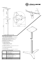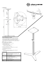
USAGE NOTES / FUNCTION
NOTE!
- Do not underestimate the weight of the monitor.
- The monitor is placed on the stand only if:
-
a. the position of the extension tube has been
- a.
secured using the catch
4.4
and in addition
- a.
to that the wing nut
4.5
has been tightened.
-
b. tray
c
and joint bracket
b.4
are securely tightened
-
c. the screw connection between the extension tube and the
- c.
joint bracket is securely tightened
8.4
, which excludes the
- c.
unintended tilting of the Monitor Desk.
- The stand (base, extension tube, tray) is NEVER to
-
be moved with the monitor on it, rather always only
-
after the monitor has been removed from the tray.
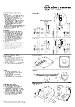
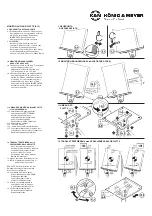
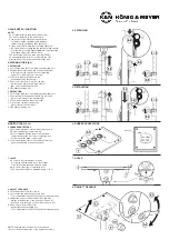
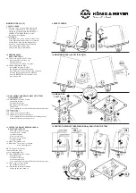
EXTENSION TUBE (4-5)
4 EXTENSION
4.1 Loosen the wing nut of the clamping bracket
b.2
a bit
4.2 Extend the extension tube
b.3
to the desired height,
4.2
in this process the catch unlocks automatically
4.2
and will not catch into place on its own.
4.3 The catch must be pressed into the
4.3
desired groove by the operator.
4.4 As soon as the catch is in place, the tube
4.4
lowers itself 2 mm, and the catch ensures
4.4
that it is not unwittingly unlocked.
4.5 Re-tighten the wing nut
5 RETRACTION
5.1 Loosen the wing nut of the clamping bracket
b.2
a bit
5.2 First pull up on the extension tube
b.3
a bit, in this
5.2
process the catch unlocks automatically.
5.3 Then let the extension tube retract and...
5.4 ...press the catch into the desired
5.4
groove until it clicks into place
5.5 Re-tighten the wing nut
MONITOR TRAY (6-12)
6 RUBBER PROTECTORS
6
a. The delivery includes 4 round rubber protectors
k
6
b. Ensure that the tray is clean and dry.
6
c. We recommend that the protectors are placed
6
c.
symmetrically at the four corners of the tray at a
6
c.
distance from the edge or the monitor.
6.1 The rubber protectors are to be removed from the
6.1
paper and adhered to the desired spots.
7 SCALE
7
a. A scale on the joint provides for exact
7
a.
positioning and the ability to use the settings
7
a.
to perfectly setup the angle time and again.
7
b. At 0° the monitor tray is completely level
7
c. The tray can be tilted to a maximum angle of 12.5°.
8 ADJUST THE ANGLE
8.1 If needed remove the lower cap
d
8.2 Loosen the two lower hexagon nuts a bit.
8.2
To accomplish this use SW13
i
Allen wrench /hexagon key.
8.3 Adjust the tray
c
to the desired position, however
8.3
always in the direction of the ledge (see Section
9
).
8.3
If needed, note the angle on the scale (see Section
7
).
8.4 Now secure the position of the
8.4
tray by tightening the safety nut.
8.4
To accomplish this use SW13
i
Allen wrench /hexagon key.
NOTE: Carefully place the monitor on the tray and
check to see if the tray moves. If yes, tighten the screws.
4. EXTENSION
5. RETRACTION
6. RUBBER PROTECTORS
7. SCALE
8. ADJUST THE ANGLE
8.
monitor
plate


