


USAGE NOTES / FUNCTION
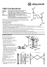
HEIGHT ADJUSTMENT
The support tubes have 7 height adjustments:
660 - 703 - 745 - 788 - 830 - 873 - max. 915 mm.
ENSURE: That both support arms are adjusted
to the same height and that the locking bolts are
always in place (the locking bolts catch).
B
DIMENSIONS
CHECK, MAINTENANCE, CLEANING
- In the event of workstation maintenance pay attention to possible risks
-
(bumped, pinched, wedged)
- To care for the product use a damp cloth and a non-abrasive cleaning agent
FAULT-FINDING (F) and REPAIR (R)
F: Stand is not stable
R: Adjust balance end caps
R: Check surface/floor for uneven surfaces
F: Height/width of the stand does not fit R: Change setting (see
R:
dimensions)
F: Equipment is not firmly
R: Check bottom of equipment for
F:
placed on the stand (unstable)
R:
uneven surfaces. Adjust the stand
R:
settings
F: The keyboard is not placed
R: Push the front rubber rings to the
F:
on the rubber base
R:
back
N
ADJUST BASES
The distances between the rubber bases can be
adjusted to the dimensions of the instrument.
Just push the rubber bases in the front to the back
until the correct distance has been selected.
ENSURE:
That the rubber base is attached to the tubes
tightly, to ensure that they are not lost. Moving the
stand requires strength.
TRANSPORTATION SETTINGS
TECHNICAL DATA / SPECIFICATIONS
Material
Steel Tubes - powder coated, black
Screws, nuts, bolts - galvanized, nickel plated
End caps, rubber base/top -TPE, Sh. 59A black
Handles, connectors - plastic; PA, PE, fiber
Load
max. 50 kg
Dimensions
width: max. 840 mm, height: 660-915 mm
support tube: ø 25 x 250 mm, foot tube: ø 30 x 380 mm
Weight
6.2 kg
Packaging
Box: 700 x 395 x 102 mm
KÖNIG & MEYER
GmbH & Co. KG
Kiesweg 2, 97877 Wertheim, www.k-m.de
18825-000-55 Rev.10 03-80-256-00 8/13
Box Dimensions
Box
6. Turn the clamp
6.
screw a bit
7. Pull the handle
7.
until the locking
7.
bolt is no longer in
7.
the drill hole
8. Extend or collapse
8.
the extension tubes
9. Place the lock pin/
9.
bolt in the desired
9.
position (hole) so
9.
that it catches and
9.
re-tighten the clamp
9.
handle
Equipment big
Equipment small