36
driven from it´s drive end using the grinder drive or an external motor. Spin grind per the
parameters below. To ensure precise clearances, do not remove knives from rotor after “in-
cutter” spin grinding.
Spare rotor set-up (“Pre-ground” method)
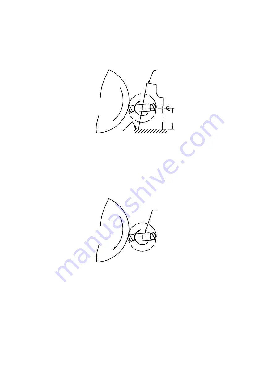
Locate spare rotor between centres of cylindrical grinder and square knives with grinding
wheel. Drive the rotor with the grinder/granulator drive and spin grind per the below para-
meters.
Cylindrical grinding parameters
Grind knife tips until the newly ground surfaces (or “lands”) are approximately 0.8 mm
(1/32’’) wide at the centre of the knife’s 174.6 mm (6-7/8”) length. Due to the 3-degree
shear angle, the lands on the knife ends will be larger than in the centre.
FIG. 5
FIG. 6
Cutter set on
outlet flange
Cylindrical grinder wheel
Grinder table
129 mm (5.08’’)
Cylindrical grinder wheel
Spare rotor be-
tween centres
Содержание KG 3000
Страница 15: ...15 FIG 10 ...
Страница 29: ...29 FIG 10 ...
Страница 43: ...43 FIG 10 ...
Страница 57: ...57 FIG 10 ...
Страница 71: ...71 FIG 10 ...
Страница 85: ...85 FIG 10 ...
Страница 99: ...99 FIG 10 ...
Страница 113: ...113 FIG 10 Sección de entrada Dirección de giro de cuchillas ...
Страница 127: ...127 ...
Страница 129: ...129 ...
Страница 130: ...130 ...
Страница 131: ...131 ...


