G210–57/3
53
3
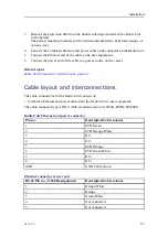
Remove the protection film from the double sided tape and attach the Radio Unit
to the helmet.
The helmet mounting brackets can be twisted and adjusted to fit helmet designs of
various sizes.
4
Connect the Combined Ethernet and power cable to the connector on the Radio Unit.
5
Connect the Ethernet end of the cable to the user equipment.
6
Connect the power end of the cable to a power source on the vessel.
Related topics
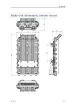
Radio Unit dimensions, helmet mount, page 57
Cable layout and interconnections
The cable connections for the Radio Unit consists of:
• Combined Ethernet and power cable from the Radio Unit to user equipment.
The cable connector type is ODU AMC standard version A10YAR-P09XCD0-0000.
Radio Unit Ethernet and power connector
Pin no.
Description/Cable colours
1
ETH Green
2
ETH Orange/White
3
DC-
4
DC-
5
ETH Orange
6
ETH Green/White
7
DC+
8
DC+
GND
GND Cable screen
Ethernet connector at user end
RJ-45 Pin no. (T-568B assignment)
Description/Cable colours
1
Orange/White
2
Orange
3
Green/White
4
Not connected
5
Not connected
Содержание MBR 144
Страница 1: ...Instruction Manual MBR 144 Personal Maritime Broadband Radio ...
Страница 2: ......
Страница 3: ...G210 57 3 March 2022 Kongsberg Seatex AS MBR 144 Personal Maritime Broadband Radio Instruction Manual ...
Страница 7: ...G210 57 3 5 Unpacking and handling 65 Storage 66 Disposal 66 Instruction Manual ...
Страница 8: ...6 G210 57 3 MBR 144 Personal ...
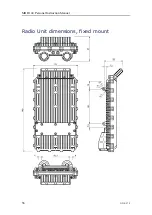
Страница 58: ...56 G210 57 3 Radio Unit dimensions fixed mount MBR 144 Personal Instruction Manual ...
Страница 59: ...G210 57 3 57 Radio Unit dimensions helmet mount Drawings ...
Страница 73: ......
Страница 74: ... 2022 Kongsberg Seatex ...

