KOMET
MicroKom®
M03Speed
12
5
6
4
1
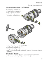
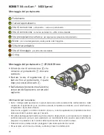
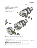
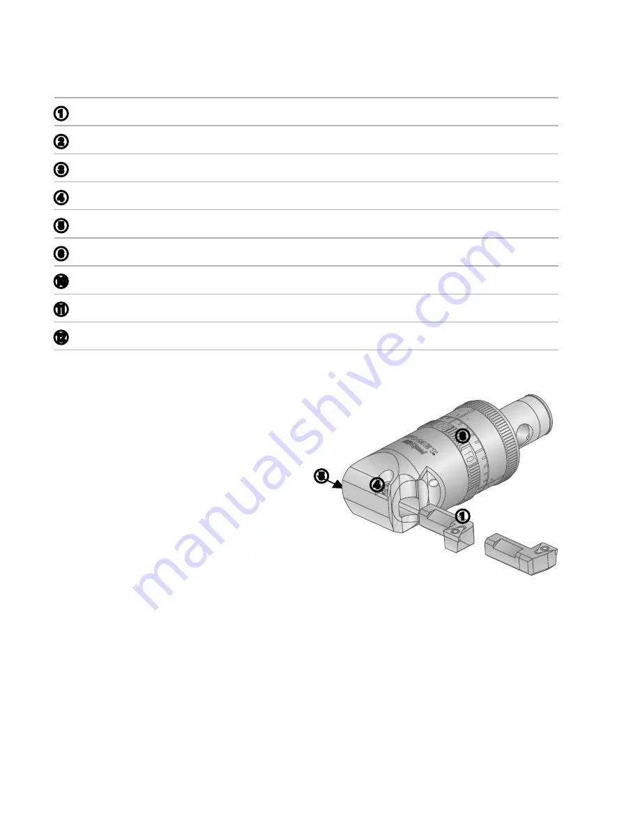
• Unscrew holding screw
4
to allow
the insert holder
1
to be replaced.
• Turn differential screw
5
until the
insert holder
1
can be pulled out.
• When fitting the insert holder check
the orientation of the cutting edge.
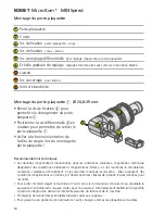
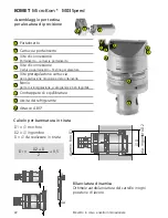
Mounting the insert holder
1
X
24.8-39 mm:
1
Insert holder
2
Holder
3
Holding screw
insert holder – holder
4
Holding screw
holder – replaceable bridge
5
Differential screw
for coarse adjustment of insert holder
6
Adjustment scale
high resolution gives easy read-off without vernier
J
Replaceable bridge
K
Clamping screw
for replaceable bridge
L
O ring
Safety notes:
• The technical notes provided in the application details depend on the environmental and application
conditions (such as machine, environmental temperature, lubrication/coolant used and desired
machining results): these are based on proper application conditions, use and compliance with the
spindle speed limits given for the tools.
• To prevent damage to machine and tool, we recommend that the drive power be calculated in
advance. The drive power which is actually available will be found in the machine manufacturer‘s
spindle speed/performance diagram.
• Safety equipment should be provided to protect personnel from flying chips.
• To ensure the best possible tool life, the insert should be changed promptly.
Mounting the insert holder


