Danaher Motion
Operation Information
32 SERVOSTAR
®
SBD-Series ST/CT Product Family
The current loop compensator circuit is a simple integrating double low pass filter (5*/19* and 6*/17*)
with a lead network (20*/18*) and the ability to scale the current feedback (10*, 9*). The current
feedback signal is scaled to 8 Volts = Drive Peak Current Rating. Resistors 9* and 10* offer the ability to
change this scaling to make the sensors more sensitive. The lead network can allow for a more responsive
current loop but lead networks tend to add noise. This circuit features the 2.4V zener diodes to clamp
noise from entering the lead network.
The current loop incorporates electrical isolation for protection from the high-voltage BUS. These current
loops also convert the output voltage to a Pulse Width Modulated (PWM) signal providing the highest
efficiency possible. The PWM center frequency 10 kHz (see CT Regen Information on page 6 for specific
details).
A simple approximation can be made by simply using a single low-pass filter designed to slow the rate-
of-change of the voltage command to prevent double-pulsing the PWM output. Components for the
tuning the current loop can be calculated with the following equation.
Resistor (5*)
≤≤≤≤
(1x10⁹ * Drive’s Peak Current Rating * Motor inductance) / (VAC*1.6)
Capacitor (19*) = 1/(625 * Resistor)
All other components should be open-circuit.
Velocity Loop
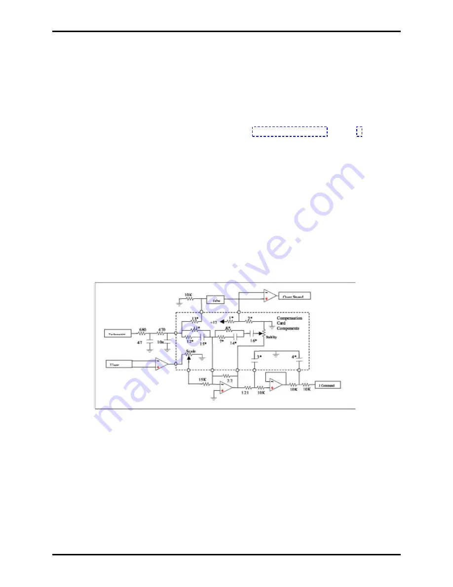
The purpose of the velocity loop is to regulate motor speed. The velocity loop compares the commanded
velocity to the actual velocity (tachometer signal) and generates a current command to bring the two in
equilibrium. The difference between actual and desired velocity is filtered through a compensator (as
shown in the following diagram).
The input to the velocity loop comes from an external analog source and is scaled with the Scale
potentiometer that provides the ability to adjust a DC Gain component. When the pot is fully clockwise,
the input is scaled so that full rated motor speed occurs with a 10V input. When the drive is used inside an
external positioner control loop, it is typical to adjust this potentiometer to allow full speed with an 8V
input to allow for overshoot.
The velocity feedback is from an external tachometer generator going through a 5kHz low pass filter
before entering the comp card where it must be scaled for the velocity loop with resistor component 11*.
The appropriate value for this resistor can be calculated using the following formula:
R11* (In Ohms)= (Tachometer Voltage (V/KRPM) * Rated Speed *1.2 *1.875) – 1,150
StockCheck.com
Содержание M-ST-009-2031
Страница 14: ...Danaher Motion System Description 8 SERVOSTAR SBD Series ST CT Product Family S t o c k C h e c k c o m ...
Страница 20: ...Danaher Motion Power Supplies 14 SERVOSTAR SBD Series ST CT Product Family S t o c k C h e c k c o m ...
Страница 33: ...Kollmorgen Hardware Installation SERVOSTAR S CD Product Family 27 CT Wiring Diagram S t o c k C h e c k c o m ...


