background image


SC-021/RC-010 Introduction Manual/ Basic Version


9


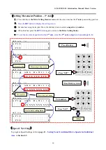
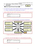
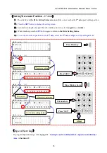
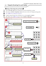
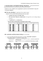
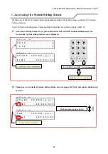
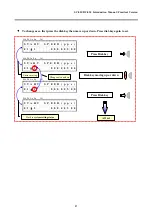
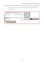
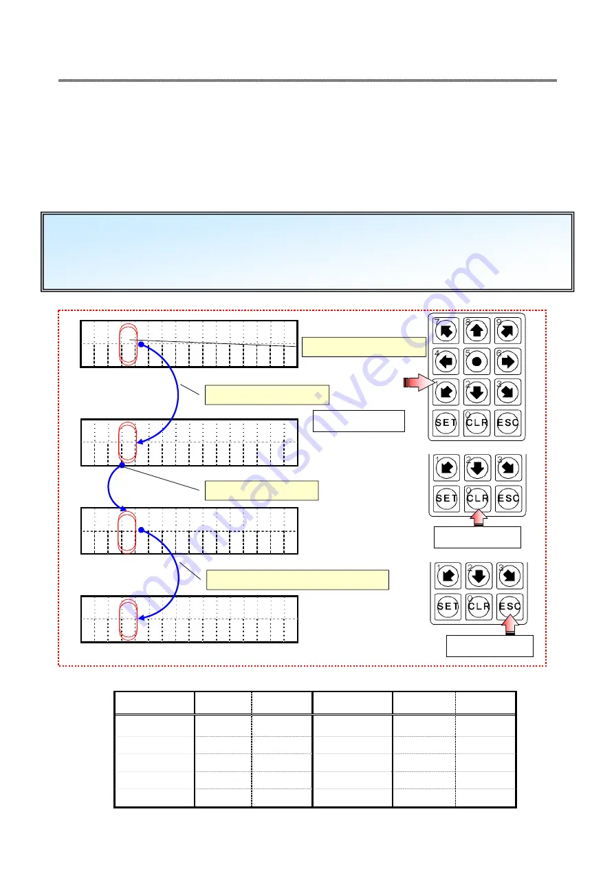
Press “SET” button to drive in Manual High Speed (Default speed: #7 on Speed settings table below).   


Press “CLR” button to drive in Manual Low Speed (Default speed: #1 on Speed setting table below).


Press “ESC” button to return to Normal speed (Default speed: #0 on Speed setting table below).


Press”ESC” 


Press”CLR” 


Press “SET” 

Md 

PE 

Ax 

Sp 


Val 


1    


0

 P 

1    


0

Md 

PE 

Ax 

Sp 


Val 


0    


0

 P 

0    


0

Md 

PE 

Ax 

Sp 


Val 


7    


0

 P 

7    


0

Md 

PE 

Ax 

Sp 


Val 


0    


0

 P 

0    


0

Change to high speed 

Change to low speed

Return to Normal speed setting


Note: 

For individual axes, see Section 1-2 “Performing a Manual Origin Return Operation “ on page 11. 

You can also program additional speed settings within the default High and Low settings. See pages 20-21 for 

more information. 


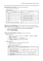
Using the Default Scan Speeds 


<Speed settings>


Display on panel

Top Speed    Startup time

Display on panel

Top Speed 

Startup time

5000

pps


24

[ms] 

6000

pps


25

[ms] 

2000

pps


21

[ms]

6

7000

pps


26

[ms] 

3000

pps


22

[ms]

7

8000

pps


27

[ms] 

4000

pps


23

[ms]

8

9000

pps


28

[ms] 

5000

pps


24

[ms]

9

10000

pps


29

[ms] 

(

The values above are default values.

 See page 26 for additional information.)


While in the Manual Scan Drive mode, you can quickly switch between the default High, Low and Normal speeds 


Default Normal Setting

Содержание RC-010

Страница 1: ...o Ltd Introduction Manual Thank you for purchasing this product Before operating this product carefully review this Manual in its entirety to ensure its proper and safe use Always keep this Manual in a convenient location for future reference Ver 1 00 Note this version does not correspond with the latest controller version ...

Страница 2: ...eries injury and or product failure 注 意 100V Use 100V AC 50 60Hz as a power supply 禁 止 This product is an electronic high precision piece of equipment Avoid operating near large machinery high voltage equipment or equipment generating strong magnetism Doing so can results in product malfunction or failure 禁 止 Do not unnecessarily remove the fixed panel and cover except in cases where adjustment or...

Страница 3: ...eed Setting 9 1 2 Performing a Manual Origin Return 10 Origin Return Operation 10 Speed Setting 11 1 3 Performing a Manual Absolute Position Movement 12 Absolute Position Movement Operation 12 Setting of Movement Position 13 Speed Setting 13 1 4 Performing a Manual Relative Position Movement 14 Relative Position Movement Operation 14 Setting of Movement Position 15 Speed Setting 15 2 0 Manually Re...

Страница 4: ...verting Pulse Number to Real Distance Angle 37 Setting Conversion Coefficient 37 Setting Number of Digits for Displayed Data 39 5 Converting Encoder Value to Real Distance Angle 40 Setting Conversion Coefficient 40 Setting Number of Digits for Displayed Data 42 Setting Encoder Pulse Multiplier 43 6 Manually Performing Encoder Correction 44 Setting Encoder Correction 44 Solutions to Encoder Correct...

Страница 5: ...I Basic Version ...

Страница 6: ... 2 0 0 Part Identification Front Rear Model SC 021 Power Switch Power Connector Cooling Fan Status Display LED Power indicator LED RC 010 Connector RS 232C Connector Drive Connector 1 PM1 Drive Connector 2 PM2 Encoder Connector 1 Encoder Connector 2 ...

Страница 7: ...R Button LCD Panel Display Magnified View Example 1 4 3 5 2 3 Drive Axis No 1 2 4 Drive Speed 0 to 9 5 Readout Numbers 1 Drive Operation S Scan O Origin Return A Absolute Position Movement R Relative Position Movement 2 Pulse Encoder Display P Amount of Motor Pulses p Conversion Data Relating to Motor Pulses E Amount of Encoder Pulses e Conversion Data Relating to Encoder ...

Страница 8: ...on 4 0 1 Status Display LED Status BUSY CW LMT CW Limit CCW LMT CCW Limit NORG NORG Sensor ORG ORG Sensor L Li ig gh ht t O On n On driving ON ON ON ON L Li ig gh ht t O Of ff f Waiting for command OFF OFF OFF OFF BUSY CW LMT CCW LMT NORG ORG 1 2 ...

Страница 9: ...SC 021 RC 010 Introduction Manual Basic Version 5 0 2 Connection Method RS 232C Cable Power Cable Motor Cable Encoder Cable 100V SC 021 Front SC 021 Rear Cable connected to RC 010 Encoder ...

Страница 10: ...urning on Power and Starting Up Power Switch Power On Logo RC 010 Version SC 021 Version Sequence of Events at Start Up Power ON Logo Version Controller Information Message and Initial State are displayed in this order Once Initial Status is displayed the initialization of SC Series is complete SC 021 Front Retrieving last data RC 010 LCD Panel N No ot te e Kohzu SC series controller will always d...

Страница 11: ... dial key Relative position movement REL See page 14 Scan Drive SCN See page 8 Md PE Ax Sp Val O P 1 0 0 P 2 0 0 Md PE Ax Sp Val R P 1 0 0 P 2 0 0 Md PE Ax Sp Val A P 1 0 0 P 2 0 0 Origin return ORG See page 10 Md PE Ax Sp Val S P 1 0 0 P 2 0 0 Changing drive mode Changing drive mode Changing drive mode Dial key moving up or down Dial key moving up or down Dial key moving up or down Dial key movin...

Страница 12: ...tton is pressed don t press any other button until completion of last movement Pushing buttons in succession causes misleading pulses in system Pulse Scanning While in the Setting Status screen press 5 to switch to Pulse Drive By default pressing any button repeatedly will drive only 1 pulse at a time See page 53 to assign a set number of pulses Once the number of pulses is set as with the Manual ...

Страница 13: ...Normal speed setting Note For individual axes see Section 1 2 Performing a Manual Origin Return Operation on page 11 You can also program additional speed settings within the default High and Low settings See pages 20 21 for more information Using the Default Scan Speeds Speed settings Display on panel Top Speed Startup time Display on panel Top Speed Startup time 0 5000 pps 24 ms 5 6000 pps 25 ms...

Страница 14: ...ual axis origin return To stop drive press the same key or the ESC button 1 2 Performing a Manual Origin Return Note Operator has the option of using the Default Scan Mode Speeds explained on page 9 of Section 1 1 or setting own default speed values explained on page 11 of this section To start drive press one of the directional keys on the keypad see diagram below N No ot te e The Origin Return M...

Страница 15: ...000 pps 25 ms 1 2000 pps 21 ms 6 7000 pps 26 ms 2 3000 pps 22 ms 7 8000 pps 27 ms 3 4000 pps 23 ms 8 9000 pps 28 ms 4 5000 pps 24 ms 9 10000 pps 29 ms The values above are default values See page 26 for additional information Press Dial key All set Press Dial key Press Dial key Md PE Ax Sp Val O P 1 0 0 P 2 0 0 Md PE Ax Sp Val O P 1 0 0 P 2 0 0 Md PE Ax Sp Val O P 1 1 0 P 2 0 0 Md PE Ax Sp Val O P...

Страница 16: ...d an L will automatically appear in display 1st axis absolute move Stop 1st axis absolute move 2nd axis absolute move 2nd axis absolute move Dual axis absolute move Dual axis absolute move Dual axis absolute move Dual axis absolute move To stop drive press the same key or the ESC button Absolute Position Movement Operation 1 3 Performing a Manual Absolute Position Movement Note Operator has the op...

Страница 17: ... Put numbers Back to drive setting status Move Dial key down Md PE Ax Sp Val A P 1 A B S R e W r i t e N N N N N N N N N N N If necessary put minus ⅱ Press the SET button to display the setting screen ⅲ Set numbers using the keypad Move the dial key down to select a negative number ⅳ When finished press the SET button again to return to the Drive Setting Status Press Dial key Press SET Press SET P...

Страница 18: ...0 P 2 0 0 1 4 Performing a Manual Relative Position Movement Relative Position Movement Operation 1st axis positive move 1st axis negative move 2nd axis negative move 2nd axis positive move 1st axis positive 2nd axis negative move 1st axis positive 2nd axis positive move 1st axis negative 2nd axis positive move 1st axis negative 2nd axis negative move Stop To stop drive press the same key or the E...

Страница 19: ... put minus Back to drive setting status Press SET Put numbers ⅱ Press the SET button to display the setting screen ⅲ Set numbers using the keypad Move the dial key down to select a negative number ⅳ When finished press the SET button again to return to the Drive Setting Status Setting Movement Position 1st Axis ⅰ Press dial key at the Drive Setting Status screen until the cursor reaches the 1st ax...

Страница 20: ...ess the SET button to display the setting screen ⅳ Set numbers using the keypad Move the dial key down to select a negative number ⅴ When finished press the SET button again to return to the Drive Setting Status ⅰ Switch to Scan Drive mode at Drive Setting Status screen by moving dial key up or down Md PE Ax Sp Val R P 1 0 0 P 2 0 0 Back to drive setting status Md PE Ax Sp Val R P 1 R E L R e W r ...

Страница 21: ...II Practical Version ...

Страница 22: ...celeration Deceleration Asymmetric trapezoidal drive Acceleration Deceleration Deceleration Acceleration S shaped drive Acceleration Deceleration Acceleration Deceleration Asymmetric S shaped drive Acceleration Deceleration Acceleration Deceleration Speeds for relative position absolute position origin return movement Available in ten speed levels SP0 to SP9 Each speed level within the default tab...

Страница 23: ...n 15 Reference signal of the encoder is set to the origin position 8 Edge of CCW limit is set to the origin position Pulse Conversion Setting converts real fed pulse into real distance angle and display Encoder Conversion Setting converts encoder value into real distance angle and display Conversion coefficient is respectively set for numerator and denominator as numerator denominator Displays to ...

Страница 24: ... Dial Key moving up or down Change setting item numbers Md PE Ax Sp Val S T A R T S P E E D p p s 0 1 1 0 0 0 0 0 5 0 0 Md PE Ax Sp Val T O P S P E E D p p s 0 2 1 0 0 0 0 5 0 0 0 1 Accessing the System Setting Screen At the Drive Setting Status screen press and hold the SET and ESC buttons simultaneously for two seconds System setting status screen is displayed Before any of the Item Codes can be...

Страница 25: ...set Press Dial key Md PE Ax Sp Val S T A R T S P E E D p p s 0 1 2 0 0 0 0 0 5 0 0 Back to system setting status Dial key moving up or down Md PE Ax Sp Val S T A R T S P E E D p p s 0 1 2 0 0 0 0 0 5 0 0 Change axis numbers Md PE Ax Sp Val S T A R T S P E E D p p s 0 1 1 0 0 0 0 0 5 0 0 Md PE Ax Sp Val S T A R T S P E E D p p s 0 1 1 0 0 0 0 0 5 0 0 Cursor moving ...

Страница 26: ...umbers using the keypad Move the dial key down to select a negative number ⅲ Press SET button again when finished ⅰ Press SET button at System Setting Status to access the data entry screen Press SET You can switch to another system setting item without having to return to the Drive Setting Status screen by moving the dial key up or down If the values entered are out of the setting range the follo...

Страница 27: ...on 23 Press ESC Close system setting status Md PE Ax Sp Val S T A R T S P E E D p p s 0 1 1 0 0 0 0 0 5 0 0 Md PE Ax Sp Val S P 1 0 0 P 2 0 0 Pressing ESC button will close the System Setting Status Screen and return to the Drive Setting Status screen ...

Страница 28: ...displayed value after angle conversion 2 13 STOP EMG 0 SLW 1 Setting of limit stop method 0 Emergency stop 1 Decelerating stop 0 14 OFFSET DATA Setting of optical offset value 0 15 PM ROTATE CHANGE Changing and setting of rotating direction 0 16 CWL NON 0 INV 1 Changing and setting of CW limit signal logic 0 17 CCWL NON 0 INV 1 Changing and setting of CCW limit signal logic 0 18 NORG NON 0 INV 1 C...

Страница 29: ...PM ENC SYNC WRITE Setting of encoder coordinate synchronization 0 35 SPD TABLE 1 300 Setting of speed table rewriting 1 36 SYS Refresh Execution of system initialization 0 37 Line 1 Edit Axis Setting of axis No on first line on LCD panel 1 38 Line 1 Edit P E Setting of conversion display on first line 0 Pulse non converted display 1 Pulse converted display 2 Encoder non converted display 3 Encoder...

Страница 30: ...SP9 System Setting Item 35 Relation between speed table and operating speed Maximum speed of speed table x Coefficient of speed table Actual drive maximum speed SP1 2 000 pps SP2 3 000 pps SP3 4 000 pps SP4 5 000 pps SP5 6 000 pps SP6 7 000 pps SP7 8 000 pps SP8 9 000 pps SP9 10 000 pps SP1 40 000 pps SP2 60 000 pps SP3 80 000 pps SP4 100 000 pps SP5 120 000 pps SP6 140 000 pps SP7 160 000 pps SP8...

Страница 31: ... SET Fix the setting Change setting item number Md PE Ax Sp Val S T A R T S P E E D p p s 0 1 1 0 0 0 0 0 5 0 0 Md PE Ax Sp Val S P D T A B L E 1 3 0 0 3 5 1 0 0 1 Md PE Ax Sp Val S P D T A B L E 1 3 0 0 3 5 1 N N N Md PE Ax Sp Val S P D T A B L E 1 3 0 0 3 5 1 0 0 1 Into data entry screen Input number Press SET ...

Страница 32: ... 1 0 0 1 Md PE Ax Sp Val S T A R T S P E E D p p s 0 1 1 0 0 0 0 0 5 0 0 Press SET Fix the setting Enter Start Speed Change setting item number Into data entry screen Enter Start Speed Press SET Rewriting of Speed Table 0 SP0 System Setting Items 1 2 A Setting the Start Speed for Speed Table SP0 System Setting Item 1 ⅰ Change setting item number to No 1 at System Setting Status by moving dial key ...

Страница 33: ... p s 0 2 1 0 0 0 0 5 0 0 0 B Setting the Maximum Speed for Speed Table SP0 System Setting Item 2 ⅰ Change setting item number to No 2 at System Setting Status by moving dial key up or down ⅱ Press SET button to access data entry screen ⅲ Using the keypad enter the desired maximum speed ⅳ Press SET button again when finished Dial key moving up or down Press SET Press SET Fix the setting Change sett...

Страница 34: ...eleration ratios with the same values 3 Asymmetric trapezoidal drive A mode to perform acceleration deceleration at constant acceleration deceleration ratios with different values 4 S shaped drive A mode to perform acceleration deceleration at acceleration deceleration ratios on the same quadric curves 5 Asymmetric S shaped drive A mode to perform acceleration deceleration at acceleration decelera...

Страница 35: ...SC 021 RC 010 Introduction Manual Practical Version 31 MEMO ...

Страница 36: ...g the keypad enter the desired acceleration time ⅳ Press SET button again when finished Rewriting Acceleration and Deceleration Times for Speed Table 0 SP0 System Setting Items 3 4 A Setting Acceleration Time System Setting Item 3 ⅰ Change setting item number to No 3 at system setting status by moving dial key up or down ⅱ Press SET button to access data entry screen Dial key moving up or down Pre...

Страница 37: ...I M E 1 0 m s 0 4 1 0 0 0 0 0 0 2 4 Into data entry ⅲ Using the keypad enter the desired deceleration time ⅳ Press SET button again when finished B Setting Deceleration Time System Setting Item 4 ⅰ Change setting item number to No 4 at system setting status by moving dial key up or down ⅱ Press SET button to access data entry screen Dial key moving up or down Press SET Press SET Fix the setting En...

Страница 38: ... the origin position 6 CCW Limit Org Origin in proximity of CCW limit is set to be the origin position 7 CW Limit Edge of CW limit is set to be the origin position 8 CCW Limit Edge of CCW limit is set to be the origin position 9 Org Only origin sensor is used 10 Now Position The present position is set to be the origin position 11 CW Limit Org Go to Zero After returning to the origin position by m...

Страница 39: ...0 9 1 0 3 Md PE Ax Sp Val O R G T Y P E 1 1 5 0 9 1 N N Md PE Ax Sp Val O R G T Y P E 1 1 5 0 9 1 0 3 Md PE Ax Sp Val S T A R T S P E E D p p s 0 1 1 0 0 0 0 0 5 0 0 Into data entry Dial key moving up or down Press SET Fix the setting Enter origin return mode No Change setting item number Input number ...

Страница 40: ... Into data entry Md PE Ax Sp Val O R G P R E S E T D A T A 0 5 1 N N N N N N N N N N N If desired change to negative Input number Setting Preset Position System Setting Item 5 ⅲ Using the keypad enter the desired preset position Move dial key down to select a negative number ⅳ Press SET button again when finished ⅰ Change setting item number to No 5 at system setting status by moving dial key up o...

Страница 41: ...t setting for the number of digits to be displayed is set to 2 Conversion results that exceed two digits will be displayed incorrectly To increase the number of digits displayed see page 39 Setting Number of Displayed Digits 4 Converting Pulse Number to Real Distance Angle Setting Conversion Coefficient System Setting Items 10 11 A Setting Conversion Coefficient Denominator System Setting Item 10 ...

Страница 42: ...n coefficient Numerator of the conversion coefficient B Setting Conversion Coefficient Numerator System Setting Item 11 ⅲ Using the keypad enter the desired coefficient numerator ⅳ Press SET button again when finished ⅰ Change setting item number to No 11 at system setting status by moving dial key up or down ⅱ Press SET button to access data entry screen Dial key moving up or down Press SET Press...

Страница 43: ...s SET button again when finished ⅰ Change setting item number to No 12 at system setting status by moving dial key up or down ⅱ Press SET button to access data entry screen Dial key moving up or down Press SET Press SET Fix the setting Enter number of digits to be displayed Prior to performing the pulse number conversion explained on pages 37 38 the operator must determine the number of digits tha...

Страница 44: ...or ⅳ Press SET button again when finished ⅰ Change setting item number to No 24 at system setting status by moving dial key up or down ⅱ Press SET button to access data entry screen Dial key moving up or down Press SET Press SET Fix the setting Enter coefficient denominator Change setting item Into data entry Input number This process allows operator to convert encoder value into real travel dista...

Страница 45: ...merator of the conversion coefficient B Setting Conversion Coefficient Numerator System Setting Item 25 ⅲ Using the keypad enter the desired coefficient numerator ⅳ Press SET button again when finished ⅰ Change setting item number to No 25 at system setting status by moving dial key up or down ⅱ Press SET button to access data entry screen Dial key moving up or down Press SET Press SET Fix the set...

Страница 46: ... SET button again when finished ⅰ Change setting item number to No 28 at system setting status by moving dial key up or down ⅱ Press SET button to access data entry screen Dial key moving up or down Press SET Press SET Fix the setting Enter number of digits to be displayed Prior to performing the encoder value conversion explained on pages 40 41 the operator must determine the number of digits tha...

Страница 47: ...he System Setting Item Code on page 24 enter the desired multiplier number 1 2 or 4 using the keypad ⅳ Press SET button again when finished ⅰ Change setting item number to No 26 at system setting status by moving dial key up or down ⅱ Press SET button to access data entry screen Dial key moving up or down Press SET Press SET Fix the setting Enter multiplication number Change setting item Into data...

Страница 48: ...ET button again when finished ⅰ Change setting item number to No 29 at system setting status by moving dial key up or down ⅱ Press SET button to access data entry screen Correction Code No Description of encoder correction 0 Encoder correction is null 1 Encoder correction is performed only once after moving is ended 2 Encoder correction is continuously performed after moving is completed C Ca au u...

Страница 49: ...tion The pulse conversion value and encoder conversion value are not the same Set the allowable range slightly larger see item code 30 below Correction does not end for a long time Set the retry numbers slightly smaller see item code 31 page 46 Driving distance at one time is too long Set the correction completion standby time slightly longer see item code 32 page 47 ⅲ Using the keypad enter the n...

Страница 50: ...R E T R Y C O U N T 3 1 1 0 0 1 0 0 Into data entry B Setting Encoder Correction Number of Retries System Setting Item 31 ⅲ Using the keypad enter the desired number of retry attempts default is set to 100 ⅳ Press SET button again when finished ⅰ Change setting item number to No 31 at system setting status by moving dial key up or down ⅱ Press SET button to access data entry screen Dial key moving...

Страница 51: ...T I M E 1 m s 3 2 1 0 0 1 0 0 Into data entry Input number ⅲ Using the keypad enter the desired standby time default is set to 100ms ⅳ Press SET button again when finished ⅰ Change setting item number to No 32 at system setting status by moving dial key up or down ⅱ Press SET button to access data entry screen C Setting the Standby Time Before Correction System Setting Item 32 Dial key moving up o...

Страница 52: ...re performed by the correction pulse numbers before moving 2 When reversing from CCW to CW direction reciprocating movements are performed by the correction pulse numbers before moving 3 In CCW direction reciprocating movements are performed by the correction pulse numbers after moving is ended 4 In CW direction reciprocating movements are performed by the correction pulse numbers after moving is ...

Страница 53: ... H P U L S E 0 7 1 0 0 0 0 0 0 0 0 Into data entry Input number Setting Number of Pulses for Backlash Correction System Setting Item 7 ⅲ Using the keypad enter the desired correction pulse number default is set to 0 ⅳ Press SET button again when finished ⅰ Change setting item number to No 7 at system setting status by moving dial key up or down ⅱ Press SET button to access data entry screen Dial k...

Страница 54: ...ow Data is Displayed on LCD Changing First Data Line System Setting Items 37 38 ⅲ Using the keypad enter the axis number to appear on the first line ⅳ Press SET button again when finished ⅰ Change setting item number to No 37 at system setting status by moving dial key up or down ⅱ Press SET button to access data entry screen A Displaying Axis No on lst Line System Setting Item 37 Dial key moving ...

Страница 55: ...rformed P 1 Pulse conversion display is performed p 2 Encoder conversion display is not performed E 3 Encoder conversion display is performed e ⅲ Referring to the table below enter the desired conversion display code using the keypad ⅳ Press SET button again when finished ⅰ Change setting item number to No 38 at system setting status by moving dial key up or down ⅱ Press SET button to access data ...

Страница 56: ...epeat steps ii iv as explained on page 50 Changing Second Data Line System Setting Items 39 40 A Displaying Axis No on 2nd Line System Setting Item 39 B Displaying Conversion Data on 2nd Line System Setting Item 40 Change System Setting item number to No 40 at system setting status screen by moving the dial key up or down Repeat steps ii iv as explained on page 51 ...

Страница 57: ...mber of Pulses in SCN Mode Scan Drive Operation System Setting Item 43 ⅲ Using the keypad enter the desired number of pulses to be performed during the scan drive operation ⅳ Press SET button again when finished ⅰ Change setting item number to No 43 at system setting status by moving dial key up or down ⅱ Press SET button to access data entry screen Dial key moving up or down Press SET Fix the set...

Страница 58: ...SC 021 RC 010 Introduction Manual Practical Version 54 MEMO ...

Отзывы: